Do you have a question about the WIKA UniTrans UT-10 and is the answer not in the manual?
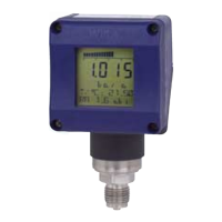
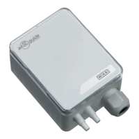
Details the physical construction, transducer, processing, and display units.
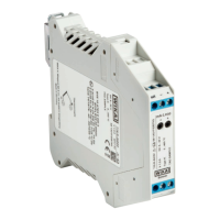
Explains operational functions for transmitters with and without displays.
Illustrates typical installation scenarios for the transmitter.
Specifies pressure ranges, output signals, accuracy, and load parameters.
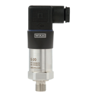
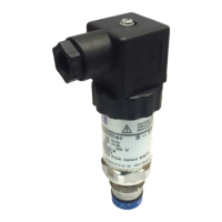
Details process connections, materials, housing, power, and conditions.
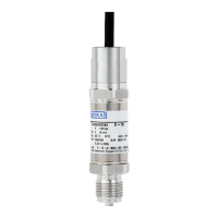
Shows an example of the transmitter's identification plate.
Guides for installing the transmitter and upgrading the display unit.
Covers housing reconfiguration and electrical connection procedures.
Explains pressure compensation for relative sensors.
Steps for preparation and description of physical button functions.
Detailed steps for zero point and span calibration with pressure.
Detailed steps for zero point and span calibration without pressure.
Covers mounting correction, integration time, and reset functions.
Information on removing and re-attaching the display unit.
Describes button functions for menu navigation and accessing the programming mode.
Lists the factory default settings for various functions.
Overview of the main menu structure for configuration.
Configuration options for the display unit.
Menu for zero and span calibration procedures.
Configuration for output signal settings like damping and inversion.
Settings for tank linearization and density correction.
Options to select the display language.
Access to service functions like loop tests and resets.
Visual representations of the transmitter dimensions.
Guide to model codes, warranty conditions, glossary, and units.
Definitions of technical terms and pressure unit conversions.
| Type | Pressure transmitter |
|---|---|
| Material | Stainless steel housing |
| Output Signal | 4...20 mA |
| Power Supply | 10...30 V DC |
| Temperature Range | -40 to +85 °C |
| Process connection | G ¼, G ½, ¼ NPT, ½ NPT |
| Electrical connection | M12 connector |
| Materials wetted parts | Stainless steel |
| Protection class | IP67 |
| Operating temperature | -40 to +85 °C |
| Storage temperature | -40 °C |