C
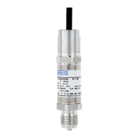
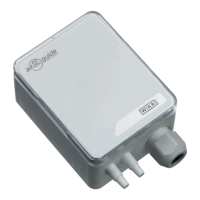
Universal Pressure Transmitter UniTrans
Product Description
Published 16.2.04
Subject to change due to technical modifications. © Copyright WIKA Alexander Wiegand GmbH & Co. KG / BRD
WIKA Alexander Wiegand GmbH & Co. KG · Alexander-Wiegand-Str. · 63911 Klingenberg ·
(09372) 132 - 710 · Fax - 706 · E-mail: support-tronic@wika.de · www.wika.de
47
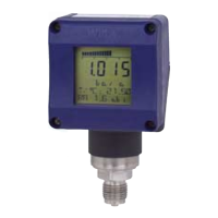
Transmitters with displa
op-
tions. These options include alarm status, dampin
nal inversion, tank lineariza-
tion and dia
es.
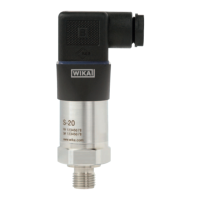
2.2 Function
The mode of operation for si
nal conversion works in the same wa
for all versions.
The pressure transducer converts the existin
pressure into an electrical si
nal. Mi-
croelectronics further process the input si
nal and produce a proportional 4-20 mA
standard si
(parameterization) and the displa
of ex-
tended functions such as inversion, dampin
, alarm status and linearization.
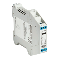
2.2.1 Functions of Transmitters without Displays
• Calibration of zero and span under pressure (see 5.3)
• Calibration of zero and span without pressure (dr
adjustment) (see 5.4)
• Settin
nal 0-40 s (see 5.5)
• Reset to manufacturer’s default values (see 5.6)
• Mountin
correction of the sensor (be
with software version 1.05)
(see section 5.4.3)
2.2.2 Functions of Transmitters with Displays
• Settable units of measurement (mbar, bar, psi, mA, %, m, mm WS) (see 6.5.1)
• Temperature and Min/Max values shown in displa
(see 6.5.1)
• Nominal pressure ran
e of the sensor shown in displa
(see 6.5.1)
• Zero and span calibration (with/without pressure) (see 6.5.2)
• Settin
nal 0-40 s (see 6.5.3)
• Inversion of the output current si
the output current value in case of alarm (3.6 mA or 21 mA) (see 6.5.3)
• Settin
the limits of the output si
nal (see 6.5.3)
• Offset of the output si
correction of the sensor
• Measurin
circuit test function (see 6.5.4)
• Reset functions (see 6.5.4)
• Password activation (see 6.5.4)
• Selectin
of a table function for the linearization of the output si
(see 6.5.6)
Display units can be easily upgraded (see chapter 4.2).
 Loading...