30
WIKA operating instructions models DIH50, DIH52
EN
14008548.05 12/2016 EN/DE
Appendix 3: ATEX/IECEx installation drawing
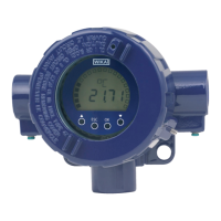
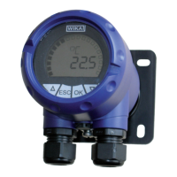
Installation drawing field indicators: DIH50-I, DIH52-I with built in WIKA digital indicator module DIH50-B
Hazardous area Non-hazardous area
Models DIH50-I, DIH52-I
Transmitter
DIH5x-B
*The internal wiring is
negligible (≤ 3 m)
Example for information only!
Provided by end-user in the
end use application!
Example for information only!
Provided by end-user in the end
use application!
Cable
Cable
Sensor
Power supply
Example: Entity parameters comparison
T32.1S.0IS: DIH50-I, DIH52-I (with power
supply and reduction):
U
i
= DC 30 V ≥ U
0
= DC 26.2 V
I
i
= 130 mA ≥ I
0
= 96 mA
P
i
= 800 mW ≥ P
0
= 551 mW
C
i
= 7.8 nF + C
iCable
≤ C
0
= 93 nF - 13.2 nF = 79.8 nF
L
i
= 100 µH + L
iCable
≤ L
0
= 4,600 µH - 1.2 µH
= 4,598.8 µH
Example: External transmitter
(e.g. T32.1S.0IS)
U
i
= DC 30 V
I
i
= 130 mA
P
i
= 800 W
C
i
= 7.8 nF + C
icable
L
i
= 100 µH + L
icable
Entity parameters DIH50-I
U
0
= DC 29 V
I
0
= 100 mA
P
0
= 660 mW (630 mW)
C
0
= value according to the
certified IS power supply
reduced by 12 nF
L
0
= value according to the
certified IS power supply
reduced by 2.2 µH
Entity parameters
DIH50-I
U
i
= DC 29 V
I
i
= 100 mA
P
i
= 660 mW (630 mW)
C
i
= 12 nF *
L
i
= 2.2 µH *
Example: Entity parameters comparison
DIH50-I, DIH52-I: KFD2-STC4 Ex1:
U
i
= DC 29 V ≥ U
0
= DC 25.4 V
I
i
= 100 mA ≥ I
0
= 86.8 mA
P
i
= 680 mW ≥ P
0
= 551 mW
C
i
= 13.2 nF
1)
≤ C
0
= 93 nF
L
i
= 1.2 µH
2)
≤ L
0
= 4,600 µH
U
0
= DC 29.8 V
l
0
= 109.2 mA
Example: Power supply
(e.g. P&F KFD2-STC4 Ex1)
U
0
= DC 25.4 V
I
0
= 86.8 mA
P
0
= 551 mW
C
0
= 93 nF
L
0
= 4,600 µH
Remark:
Due to the segregation requirements
of the applied standards, IS-supply-
and signal-circuit and the IS sensor
circuit shall be considered as being
galvanically connected to each other;
functional separation provided.
Summarised requirements for field indicator WIKA DIH50-I, DIH52-I:
Special conditions for a safe use: None
Ambient temperature range and temperature classification
field indicator DIH50-I, DIH52-I
Ambient
temperature
range
IIC (-50)
1)
-40 °C ≤ T
a
≤ +85 °C (T4)
(-50)
1)
-40 °C ≤ T
a
≤ +70 °C (T5)
(-50)
1)
-40 °C ≤ T
a
≤ +55 °C (T6)
IIIC (-50)
1)
-40 °C ≤ T
a
≤ +40 °C (P
i
= 680 mW)
(-50)
1)
-40 °C ≤ T
a
≤ +70 °C (P
i
= 650 mW)
1) The values in brackets are valid for special low temperature versions
(only limited transmitter combination for series DIHxx-I possible).
Marking field indicator DIH50-I
ATEX
IECEx
II (1) 2G Ex ia [ia Ga] IIC T4/T5/T6 Gb
II (1) 2D Ex ia [ia Da] IIIC T120 °C Db
1) C
i
= 13.2 nF + C
i
-value of the connected and certified
transmitter + C
iCable
2) L
i
= 1.2 µH + L
i
-value of the connected and certified
transmitter + L
iCable
14041464.02