Do you have a question about the WIKA DIH50-F and is the answer not in the manual?
Explains the meaning of warning and caution symbols used in the manual for safety.
Details the specific applications and purpose of the field indicators DIH50, DIH52, and DIH62.
Defines the required qualifications and expertise for personnel handling the instrument safely.
Provides specific safety guidelines for instruments operating in ATEX-certified hazardous areas.
Highlights particular risks associated with hazardous media and operational environments.
Details the product label and safety marks present on the instrument.
Explains the meaning and compliance of various certification marks like CSA, CE, ATEX, and FM.
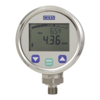
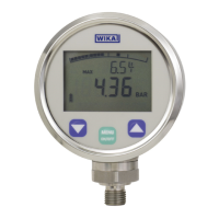
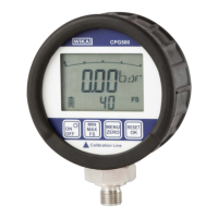
Details display principles, measured value presentation, bar graph, information line, and indication range.
Describes access control, parameter settings, and commands for HART communication.
Specifies environmental limits including temperature, vibration, and shock resistance.
Covers EMC compliance and the physical characteristics of the instrument's field case.
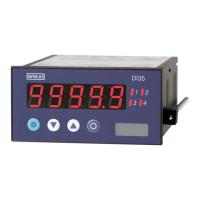
Explains the purpose and operation of the DIHxx field indicators as external display and operating units.
Lists and describes the different models and their respective features, including Ex protection.
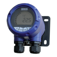
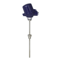
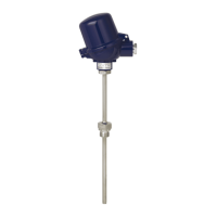
Details the construction and mounting of the DIH50/DIH52 basic modules with diagrams.
Describes the case and terminal blocks for DIH50/DIH52 field indicators with diagrams.
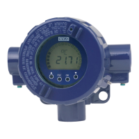
Illustrates the different single chamber case options for the DIH62 field indicator.
Confirms suitability for SIL-rated safety applications and references manufacturer's statement.
Instructs the user to cross-check the delivered items against the delivery note.
Instructions for checking and reporting damage incurred during transport.
Advice on keeping packaging for protection during transport or for repairs.
Specifies permissible storage temperatures, humidity, and factors to avoid.
Details the available operating modes: HART® slave and HART® master/multidrop.
Explains operation as a HART® slave, including automatic adaptation and symbol indication.
Describes the HART® master mode for modifying transmitter settings and the connection process.
Covers Multidrop operation for DIH52/DIH62 and manual settings in Basic mode for all models.
Illustrates the front panel layout, display elements, and operating keys for DIH50/DIH52 and DIH62.
Highlights critical safety warnings for electrical connection, including power disconnection and ESD prevention.
Provides guidance on cable selection, gland usage, and connecting cable screens to earth.
Details the electrical connection for DIH50 and DIH52 models, including diagrams and polarity protection.
Explains the connection procedure for the DIH62 field indicator, including cable gland and wire stripping.
Presents a detailed wiring diagram and important notes for connecting transmitters and power supply.
Provides a visual guide to the main menu, submenus, and available options for configuring the instrument.
| Protection class | IP65 |
|---|---|
| Measuring range (humidity) | 0...100% RH |
| Output signal | 4...20 mA |
| Accuracy (humidity) | ±2% RH |
| Accuracy (pressure) | ±0.5% FS |
| Process connection | G1/2, 1/2" NPT |
| Material | Stainless steel |
| Operating temperature (pressure) | -20...+80 °C / -4...+176 °F |