13
■
If possible, the entire length of the stem should be exposed to the
temperature being measured. However, at least the length of the
active part that corresponds to the length of the gas expansion
vessel (active length).
■
In pipelines or other measuring points, the temperature probe must
be positioned as far towards the ow as possible.
■
Errors in thermal conduction occur if the area where the temperature
is to be measured is so small, that the mass of the temperature
probe acts as thermal capacity. Errors in thermal conduction may
also occur if the insertion depth is insucient, if the mounting ttings
are connected to a good thermal conductor (metal plate or similar)
and there is a considerable dierence in temperature between the
measuring and mounting element temperatures.
■
Mount the indicator case free from vibration. If necessary, it is
possible to isolate the installation from the mounting point, e.g. by
installing a exible connection line between the measuring point and
the thermometer and mounting the instrument on a suitable bracket.
If this is not possible, the following limit values must not be exceeded:
Frequency range < 150 Hz
Acceleration < 0.5 g (5 m/s
2
)
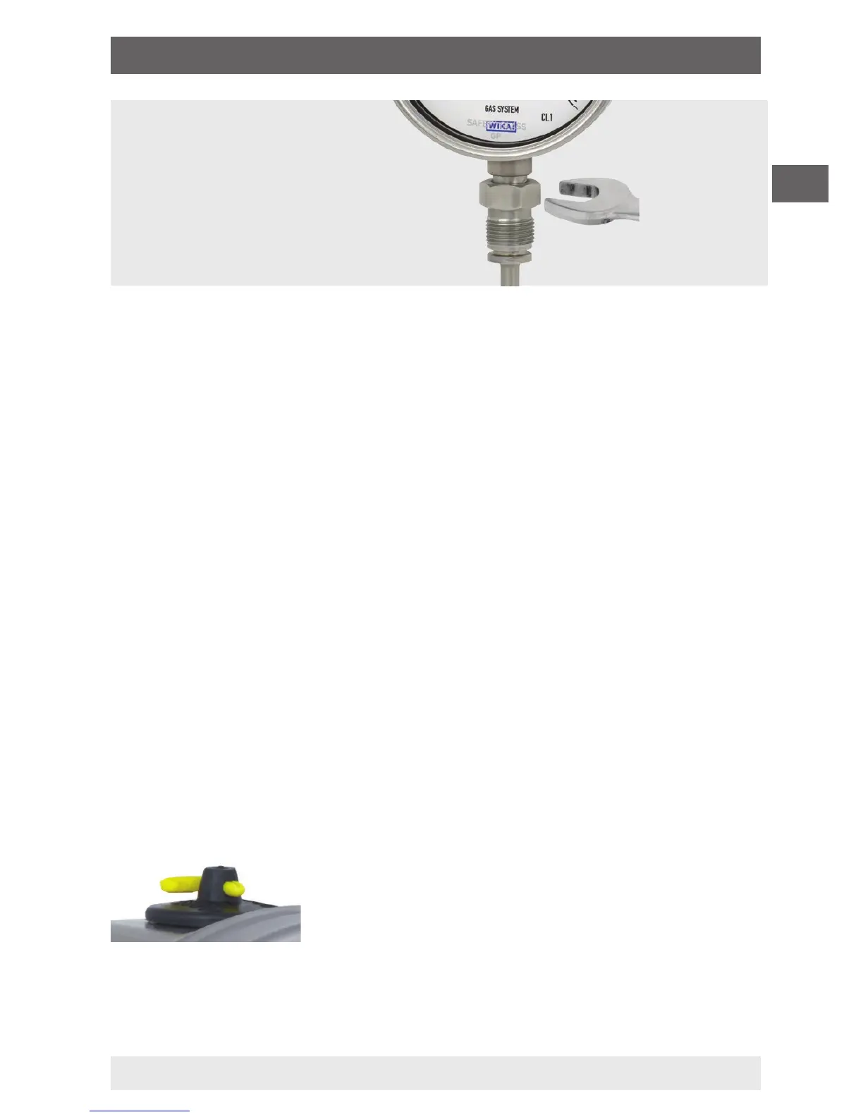
After installation, set the vent valve (if available)
from CLOSE to OPEN.
Installation with
open-ended spanner
5. Commissioning, operation

 Loading...