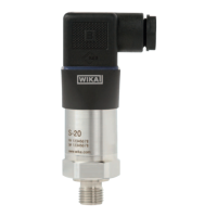
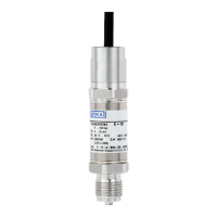
45WIKA operating instructions pressure transmitter, model IS-3
MM/YYYY country code based on 14095850.02 12/2014 EN/CN
EN
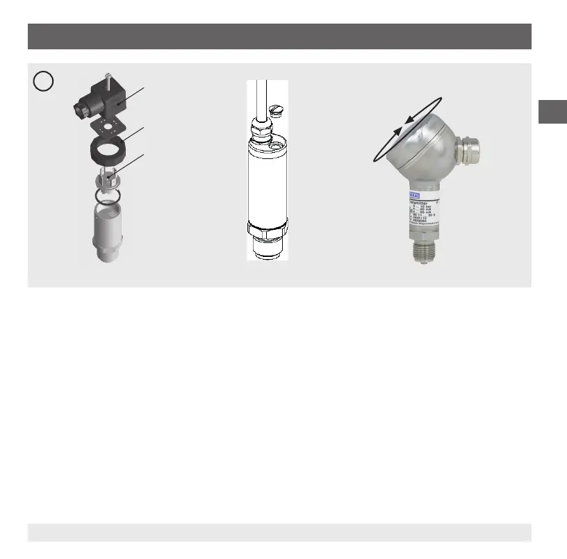
A
Clamping nut Screw
7.2 Adjustingthezeropoint(gureB)
1. Connect the instrument connector (3) to the power supply and a display unit (e.g. ammeter, voltmeter) according to
the connection diagram.
2. Go to the start of the measuring range.
3.
Using potentiometer “Z”, adjust the minimum output signal (e.g. 4 mA)
7.3 Adjustingthespan(gureB)
1. Connect the instrument connector (3) to the power supply and a display unit (e.g. ammeter, voltmeter) according to
the connection diagram.
2. Go to the end of the measuring range.
3.
Using potentiometer “S”, adjust the maximum output signal (e.g. 20 mA)
4. Check the zero point and if there is any deviation, re-adjust it.
5. Repeat the procedure until the zero point and the span are set correctly.
Field case
7. Adjusting the zero point and span
 Loading...