3345267.08 06/2011 GB/D
28 WIKA operating instructions RTD and TC, intrinsically safe designs
GB
To help select the minimum neck length, the following standard values have been determined.
Maximum temperature of the
medium
Recommendation for
dimension N
Recommendation for
dimension X
100 °C - -
135 °C 20 mm 20 mm
200 °C 50 mm 50 mm
>200 °C ≤ 450 °C 100 mm 100 mm
WARNING!
For reasons of work safety and saving of resources, hot surfaces should be protected
against accidental touch and energy loss by means of insulation.
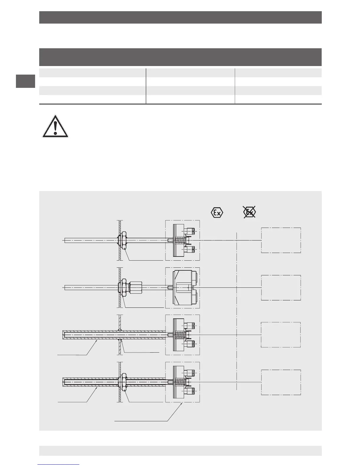
7.4 Mounting examples in hazardous areas
7.4.1 Possible installation methods with the marking II 1G Ex ia IIC T6 Ga or
II 1D Ex ia IIIC T65 °C Da
7. Information on mounting, operation in hazardous areas (Europe)
Zones 0, 1, 2 or Zones 20, 21, 22
Hazardous area
Safe area
Thermowell
Thermowell
welded
TWxx
TWxx
Process
connection
Connection head/
Field housing
Tx10-B
Tx10-C
Tx10-C
Tx10-D
Tx10-H
Tx10-H
Option:
with built-in
transmitter:
e.g. T32
Tx10-A
Process
connection
Compression
tting
Associated
electrical equipment
Intrinsically
safe supply or
suitable barrier
e.g. transmitter power supply
KFD2-STC4-Ex1
WIKA Art. No.: 2341268
e.g. Zener barrier
Z954 for Pf100-3L
WIKA Art. No.: 3247938
Intrinsically
safe supply or
suitable barrier
Intrinsically
safe supply or
suitable barrier
Intrinsically
safe supply or
suitable barrier
Tx10-A
Tx10-A
Tx10-A
 Loading...