WIKA operating instructions RTD and TC, intrinsically safe designs
3345267.08 06/2011 GB/D
29
GB
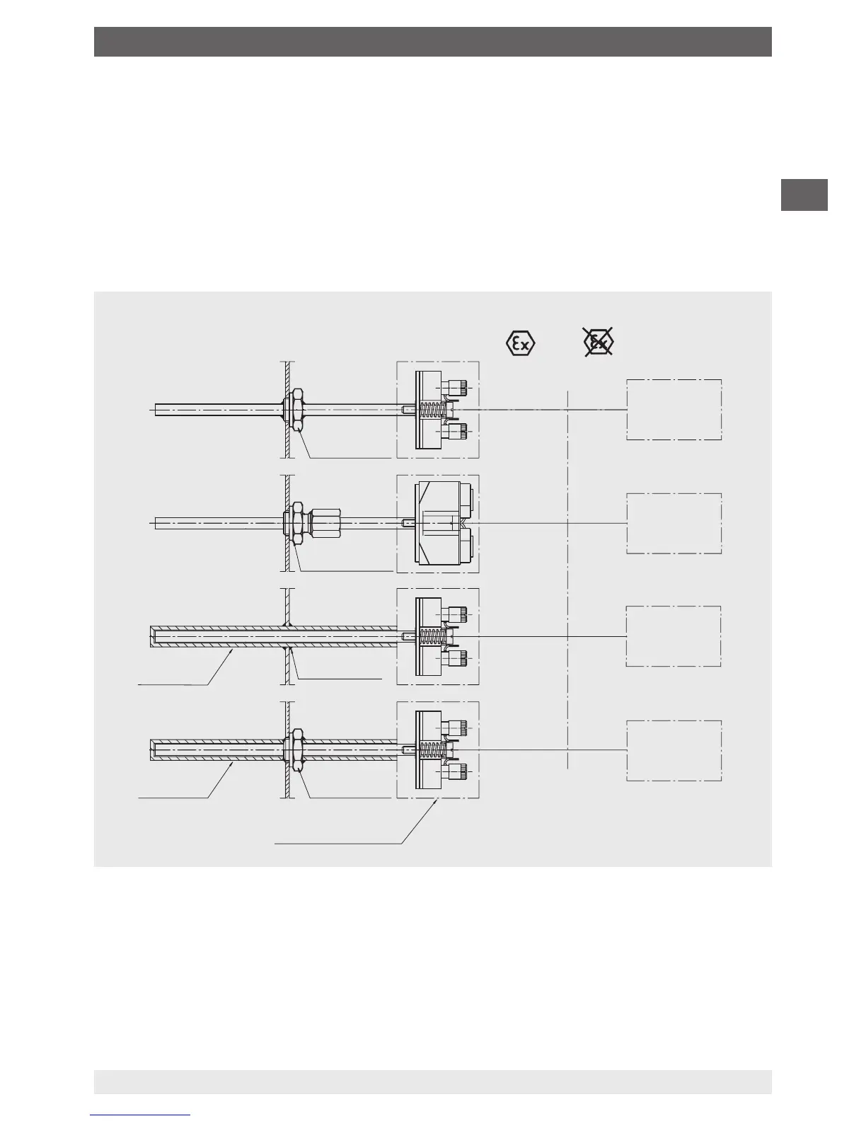
Zones 1, 2 or
Zones 21, 22
Hazardous area
Safe area
Thermowell
Thermowell
welded
TWxx
TWxx
Process
connection
Connection head/
Field housing
Tx10-B
Tx10-C
Tx10-C
Tx10-D
Tx10-H
Tx10-H
Option:
with built-in
transmitter:
e.g. T32
Tx10-A
Process
connection
Compression
tting
Associated
electrical equipment
Intrinsically
safe supply or
suitable barrier
e.g. transmitter power supply
KFD2-STC4-Ex1
WIKA Art. No.: 2341268
e.g. Zener barrier Z954
for Pf100-3L
WIKA Art. No.: 3247938
Intrinsically
safe supply or
suitable barrier
Intrinsically
safe supply or
suitable barrier
Intrinsically
safe supply or
suitable barrier
Tx10-A
Tx10-A
Tx10-A
Zones 0, 1, 2 or
Zones 20, 21, 22
The sensor together with housing or connection head is located in Zone 0 (Zone 20). An Ex
ia type circuit must be used. A zone separation is deemed to exist if the process connection
guarantees a suciently tight gap (IP 67) between the less hazardous zone and the Zone 0.
Examples of suitable process connections include gas-tight standardised industrial anges,
threaded connections or pipe connections.
7.4.2 Possible installation methods with the marking II 1/2 Ex ib IIC T6 Ga/Gb or
II 1/2 D Ex ib IIIC T65 °C Da/Db
The sensor or thermowell tip protrudes into Zone 0. The housing or connection head is in Zone 1
(Zone 21) or Zone 2 (Zone 22). It is sucient to use an Ex ib type circuit.
Zone separation is guaranteed if suciently-tight (IP 67) process connections are used.
Examples of suitable process connections include gas-tight standardised industrial anges,
threaded connections or pipe connections.
7. Information on mounting, operation in hazardous areas (Europe)
 Loading...