WARNING: rotate the wheel without pushing too much the blade
against it.
The instrument is normally delivered adjusted on the minmum
value of its range (factory calibration).
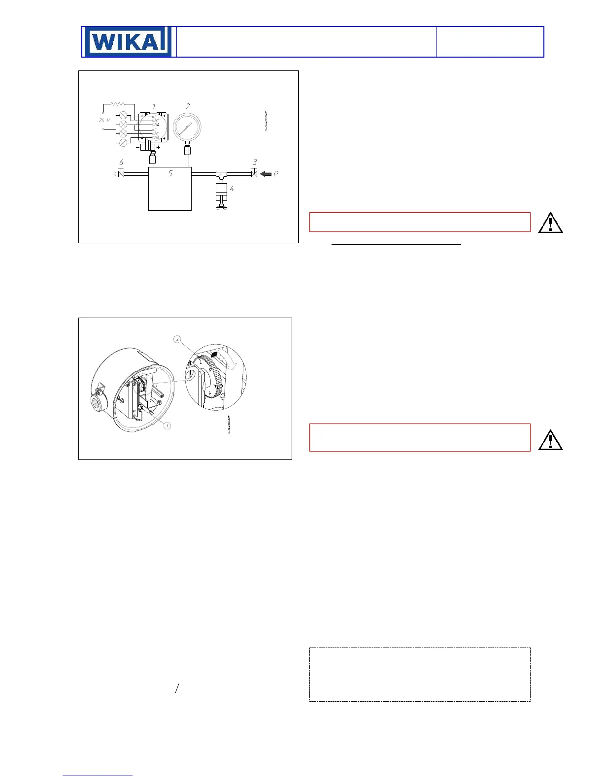
Calibration of dead band
The calibration of the dead band is obtained using the following
procedure:
1 - Raise pressure in the circuit until reaching the set point and
record its value (Pi).
2 - Reduce pressure in the circuit until reaching the reset point
and record its value (Pr).
3 - The difference Pi - Pr = Va represents the dead band factory
adjusted value.
4 - Rotate the adjustment wheel in the sense shown in Fig. 6
placing the red notch in horizontal position
5 - Repeat operations 1 and 2 and measure the new dead band
Vb.
6 - By comparing the values Va and Vb approximately determine
the color of the wheel notch to be placed on the mark.
7 - Place the notch and measure the obtained dead band.
8 - Proceed by successive approximations until reaching the
desired dead band value with enough accuracy.
9 - Then proceed with the set point calibration
Example: The dead band increase corresponding to the rotation
from A to B is given by: Vb - Va =I
The desired dead band V will be approximately in the position
indicated by the value
which expresses:
- By units, the wheel notches (1=one black notch, 2=one red
notch, 3=one yellow notch, 4=one blue notch, 5=one green
notch, 6=two black notches).
- By decimal digits, the percentage middle position between
the located notch (of units) and the following one.
6.6 FINAL OPERATIONS
Disconnect the instrument from the calibration circuit.
1.1.1 Weatherproof pressure switches (Models DW)
Take the cover, ensure that the sealing gasket is correctly fitted
into its seat, and insert the cover onto the case, with the blocking
gap positioned in correspondence to the blocking bracket.
Turn the cover clockwise closing it tightly. Mount the blocking
device as in Fig. 4. Mount on pressure connection and cable
entry the protection caps supplied with the instrument.
1.1.2 Flameproof pressure switches (Models DA).
Insert the closure plugs of the adjustment screw access holes,
block them using the internal device and if necessary seal them
with plumbing. Screw on the cover and block it using the
headless screw with which it is equipped (Fig. 5)
1.1.3 Final operations
Mount on pressure connection and cable entry the protection
caps supplied with the instrument.
Caution: The protection caps should only be definitively
removed during the connection steps (see § 7).
7. MOUNTING AND CONNECTIONS
7.1 MOUNTING
Surface mount the instrument by means of the holes provided,
or pipe mount using the appropriate bracket (see Fig. 14,15 e
16). In case of surface or panel or rack mounting the instruments
can be mounted side by side (see Fig.19).
The chosen position must be such that vibrations, the possibility
of shocks or temperature changes are within tolerable limits. With
gas or vapour process fluid, the instrument must be positioned
higher than the pipe inlet (see Fig.18). With a liquid process fluid,
the instrument can be positioned higher or lower, indifferently
(see Fig.17 e 18).
7.2 INSTRUMENT WITH DIAPHRAGM SEALS
When the pressure switch is mounted on diaphragm seal with
capillary and the set point is less than 10 bar, the gap (distance
h) between one diaphragm seal and instrument or between the
two diaphragm seals generates a column of liquid, whose
pressure equivalent constitutes a drift of set point. The set point
has to be adjusted consequently.
7.3 PRESSURE CONNECTIONS
Connecting lines are an integral part of the instrument in
transmitting the measured variable from the measuring point to
the instrument.
For a correct installation it is necessary to:
Mount a shut-off valve with drain (root valve) on each process
pipe inlet to allow the instrument to be excluded and the
connection tubing to be drained. It is recommended that said
valve has a capstan blocking device aimed at preventing it being
activated casually and without authorisation.
Mount a 3 valve manifold near the instrument to permit possible
functional verification on site and removal of the instrument. It is
recommended that the manifold is made up of two service valves,
one by-pass valve and two suitably connected drain plugs. The
three valves with the drains can be reunited by a single device
called a “Three valve manifold” (see fig.21 for flanged manifold
valve and fig.22 for direct manifold valve).
Mount a three piece joint onto the threaded attachment of the
instrument to permit the easy mounting or removal of the
instrument itself.
Carry out the connection using a flexible tube in such a way that
variations in the temperature of the tube itself do not force the
instrument attachment.
Ensure that all the pressure connections are airtight. It is
important that there are no leakage in the circuit.
Close root valves, the two service valves, drain plugs and open
the by-pass valve.
NOTE: if the instrument is used for level control in tanks under
pressure it is recommended that installation is carried out
according to the diagram in figure 23 and 24
In case of installation as per fig 23 ensuring that the seal pot B
has a sufficient capacity to maintain the liquid level at the
maximum height over time.
 Loading...