7 of 9
15. TROUBLESHOOTING
IMPORTANT NOTE: operations involving replacement of essential components must be carried out at our workshop, especially for
instruments with flameproof certificate; this is to guarantee the user the total and correct restoration of the product original characteristics.
Air bubbles in the connection lines (condensation in
the case of use of gas; excluding versions DW10
and DA10)
Solid particles deposited inside the measurement
chambers of the instrument (excluding versions
DW10 and DA10)
Permanent deformation of the sensitive element
due to fatigue or non-tolerated over-ranges
Variation of the elastic features of the sensitive
element due to its chemical corrosion.
Leakage of filling fluid (excluding versions DW10
and DA10).
Drain using the appropriate plugs
Dismount the measurement chambers and clean
them (during the mounting phase the screw locking
couple is 80 N/m)
Recalibrate or replace the sensitive element.
Recalibrate or replace the sensitive element with
another made of a suitable material. If necessary
apply a fluid separator
Send to the constructor for checking
Clogged or obstructed connection line.
Root or service valve partially closed.
Too viscous fluid.
Check and clean line.
Open valve.
Provide instrument with suitable fluid separator.
No actuation or
undue actuation
Root or service valve closed.
By-pass valve open.
Microswitch contacts damaged.
Loosened electrical joints.
Interrupted or short-circuited electrical line.
Open the valve.
Close the valve.
Replace the microswitch.
Check all electrical joints.
Check the conditions of the electrical line.
Accidental shocks or excessive mechanical
vibrations.
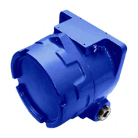
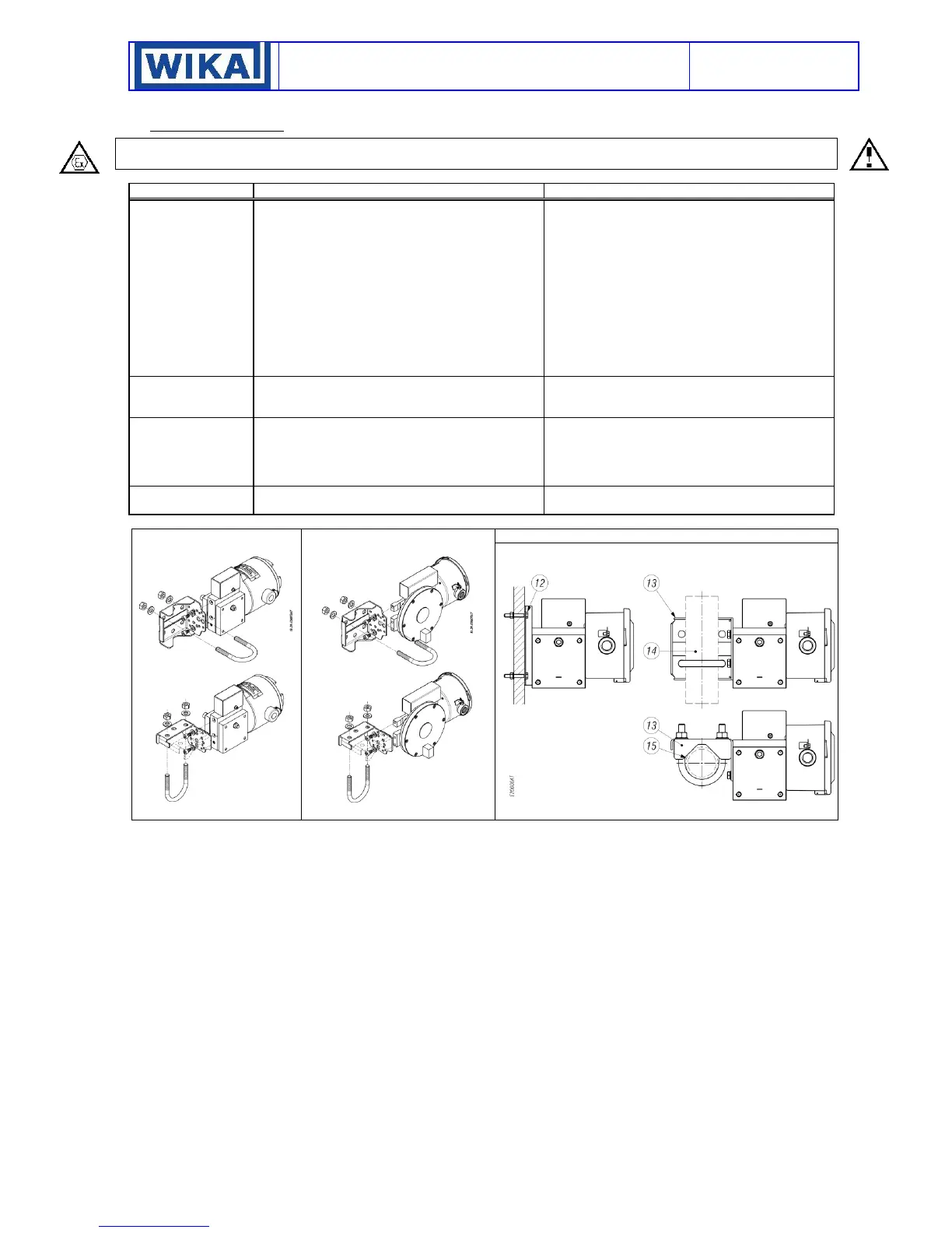
Fig.14 – DW-DA – Mounting
of the brackets for 2” pipe
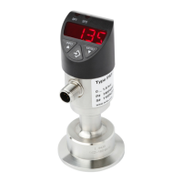
Fig.15 – DW10-DA10- Mounting
of the brackets for 2” pipe
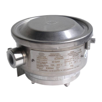
Fig. 16 - Example of mounting
 Loading...