5 of 9
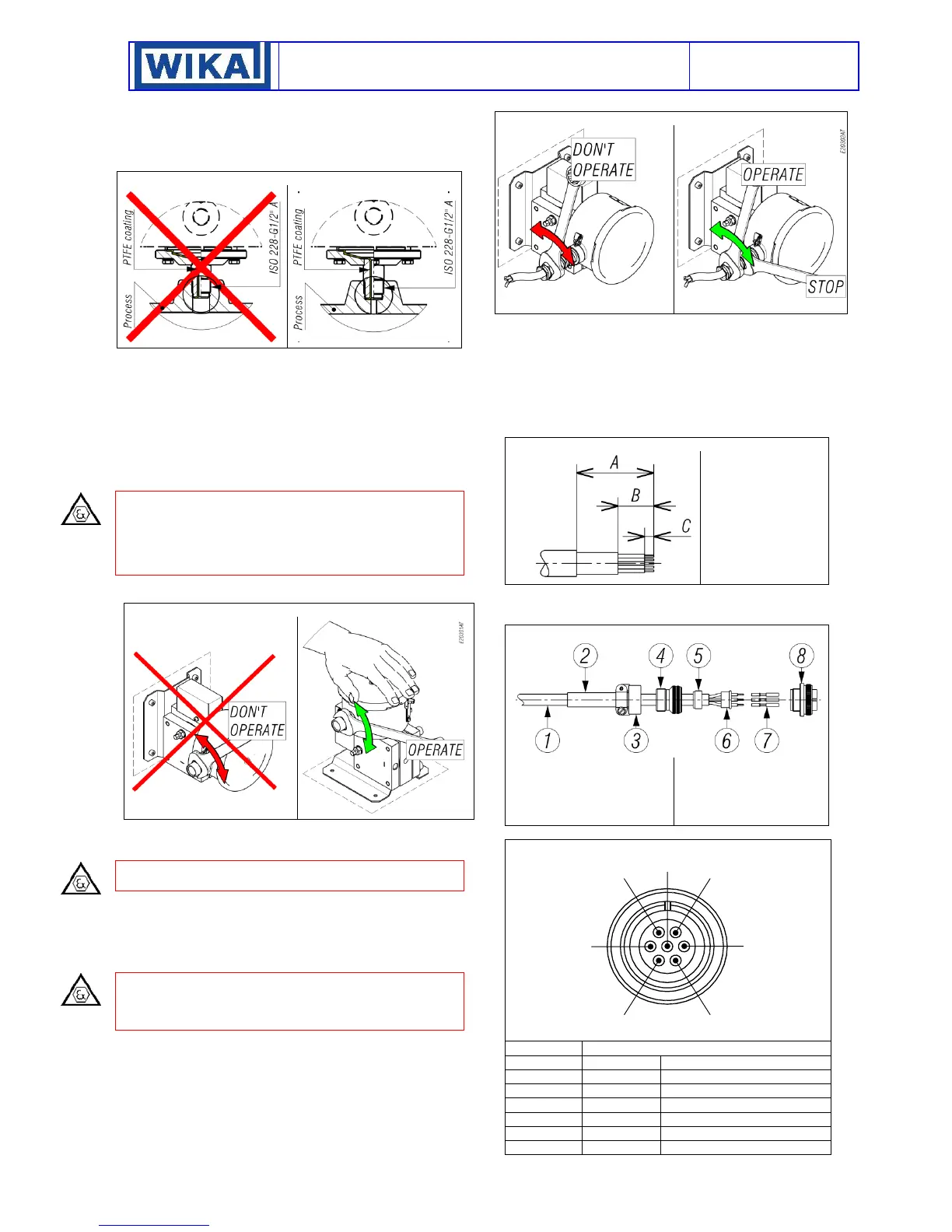
7.4 INSTRUMENTS WITH PROCESS CONNECTION
COATED WITH PTFE
The pressure connection must be made in such a way that the
part protruding from the instrument have to be used as a sealing
ring.
Fig.8 - Instrument with process connection coated with PTFE
7.5 ELECTRICAL CONNECTIONS
It is recommended to carry out the electrical connections
according to the applicable standards. In case of flameproof
instrument see also the Standard IEC-60079-14. If the electrical
connection is carried out in a protected tube, it shall be made so
that condensate is prevented from entering instrument enclosure
To guarantee the ingress protection IP66 and prevent loosening
of the blocking joint or cable glands, it is prescribed to seal the
threads with an anaerobic sealant. For example, use a sealant
like Loctite ® 542.
CAUTION: fittings used for the electrical connection of the
flameproof instruments shall be certified according the IEC or EN
standards and shall guarantee instrument degree of protection
(IP66).
In the case of Gk threads, this is made in accordance with
standard UNI-EN 60079-1 (Italian national variant).
The installation of the cable gland or three-piece joint should be
as per fig 9.
Fig. 9 – Installation of electrical connection
With the instrument into the final position provided that the
electric line is not energize, remove the cover and make the
electrical connection to the terminal block (see Fig. 2).
If the ambient temperature exceeds 60 °C is recommended to
use cables suitable for operating temperatures of at least 105 °C.
Flexible cables with a maximum section of 1,5 mm
2
(16AWG) are
recommended using the pre-insulated crimp ring terminal.
Do not touch the adjustment screws and do not bend the
elastic microswitch supports in order to prevent the instrument
calibration being altered. Ensure that no deposits or wire ends
remain inside the case.
Warning: The instrument may be equipped with one or two micro
switches SPDT type. All the electrical connection must be part of
intrinsically safe circuits. The relevant parameters for intrinsic
safety are listed on the nameplate of the instrument.
The tightening of the cable gland or the three-piece joint must be
performed as shown in Fig. 10.
Fig. 10 – Installation of the cable gland
As soon as connection steps are completed, mount the cover on
and make sure it is tight and blocked See fig 4 and 5.
7.5.1CONNETTOR 7 POLES TYPE MIL-5015 FOR WEATHER
PROOF INSTRUMENT
The free connector, supplied with the instrument, is able to
accept multicore cables with maximum outer diameter 11 mm. It
is recommended flexible cables with single-conductor with a
maximum section of 1.5 mm2 (16AWG).
The cable have to be prepared as per fig. 12
Fig. 12 – Cable preparation
A= 53mm
B= 30mm
C= 6,5 mm
The single stripped conductor has to be crimped with each
contact pin. For the electrical connections and for the assembly
follow Fig.13.
Fig. 13 – Free connector assembly
1- Cable
2- Heat Shrink Boot
3- Clamp
4- Extender
5- Ferrule
6- Insulator for pin
contacts
7- Pin contacts
8- Shell
The wiring diagram is according Fig.14.
Fig. 14 – Wiring diagram MIL C-5015
Internal grounding connection
Once the crimping and assembly activities of the free connector
are finished, make sure that all the parts are tight. Screw the

 Loading...