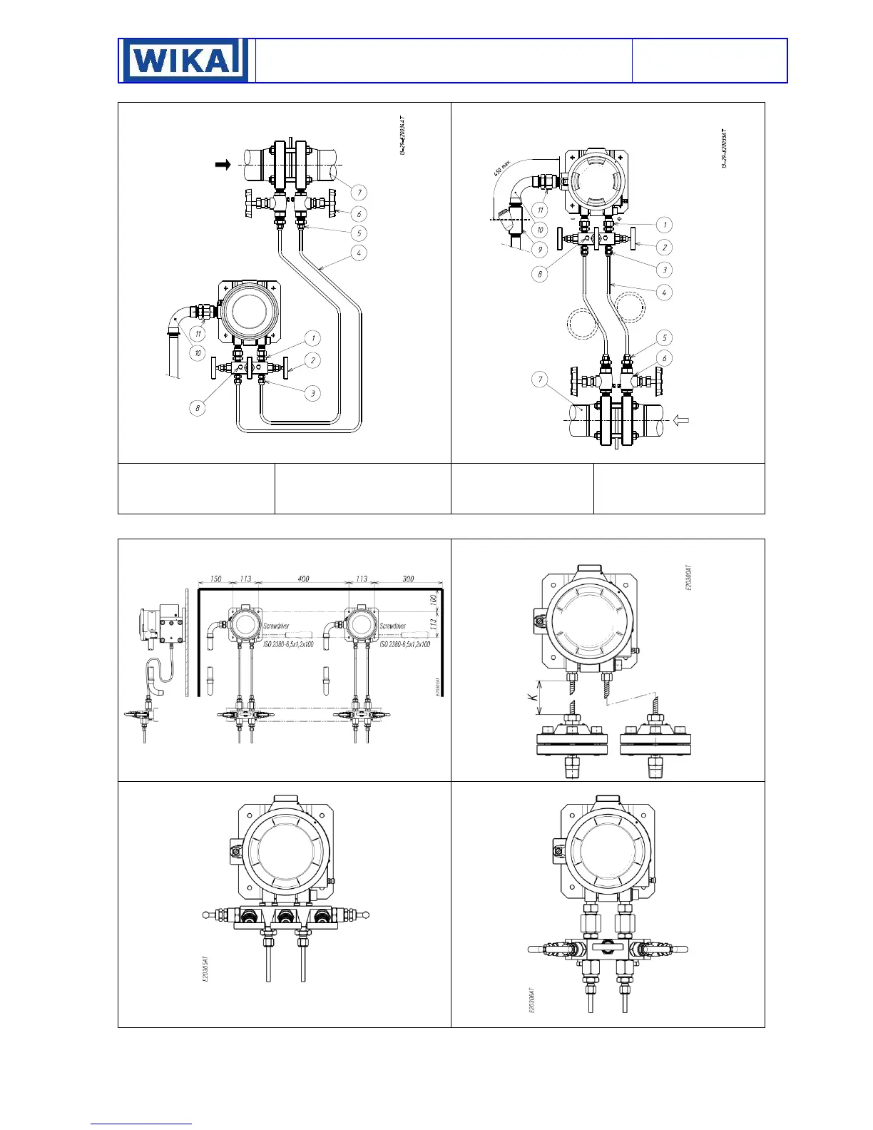
Fig. 17 - Example of connections -
Fig. 18 - Example of connections -
1 - Three pieces fitting
2 - Three valves manifold
3 - Three pieces fitting
4 - Piping
5 - Three pieces fitting
6 - Root valve with drain
7 - Filter or nozzle
8 - Check inlet and drain plug
9 - Blocking joint
10 - Curve
11 - Three pieces fitting
12 - M6 screws (N°4)
13 - Bracket for 2” pipe
14 - Vertical pipe
15 - Horizontal pipe
NOTE With gas or vapour process fluid, the instrument must be positioned higher than the pipe inlet (see Fig. 18). With a liquid process
fluid, the instrument can be positioned higher or lower, indifferently (see Fig. 17 e 18).
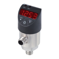
Fig. 20 – Instrument with diaphragm seals version
DW496/DW197 and DA496/DA197
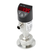
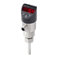
Fig. 21 – Mounting of flanged manifold valve
Fig. 22 – Mounting of direct manifold valve (½ G threads)
 Loading...