\VII.I.SS
hlODEI.
"Alli" !<-TON
4
x
+
C;O\'EI<NMENT TRIJCK
0100-21
Removing and Replacing of Valve Guide
\\:lien reinoviiig tlie valve giiides iise
a
valve
giiide piillcr sucli as shown
iii
Fig.
5
to prevent
damage to cylinder bloclc. If a regular piiller
is not avuilable, a siiitahle tool can be made from
a
2"
pipe.
(i"
long aiid
a
96"
bolt
10"
to
12"
long witli
a
long tlireaded end,
s
small hexagon nut
wliicli wil1 pass tliroiigli tlie hole in tlie cylinder
block
an<l a
2"
weslier with a
36''
Iiole in it.
Tlie valve giiides are installed witli a replacer ar a
driver as
shnwn in Fig.
G.
Takiiig
a
piece of half
inch roiintl stock
C,"
Icing and toriiiiig down one end
to
w
diameter
I"
Inrig wil1 make n suitable rlriver.
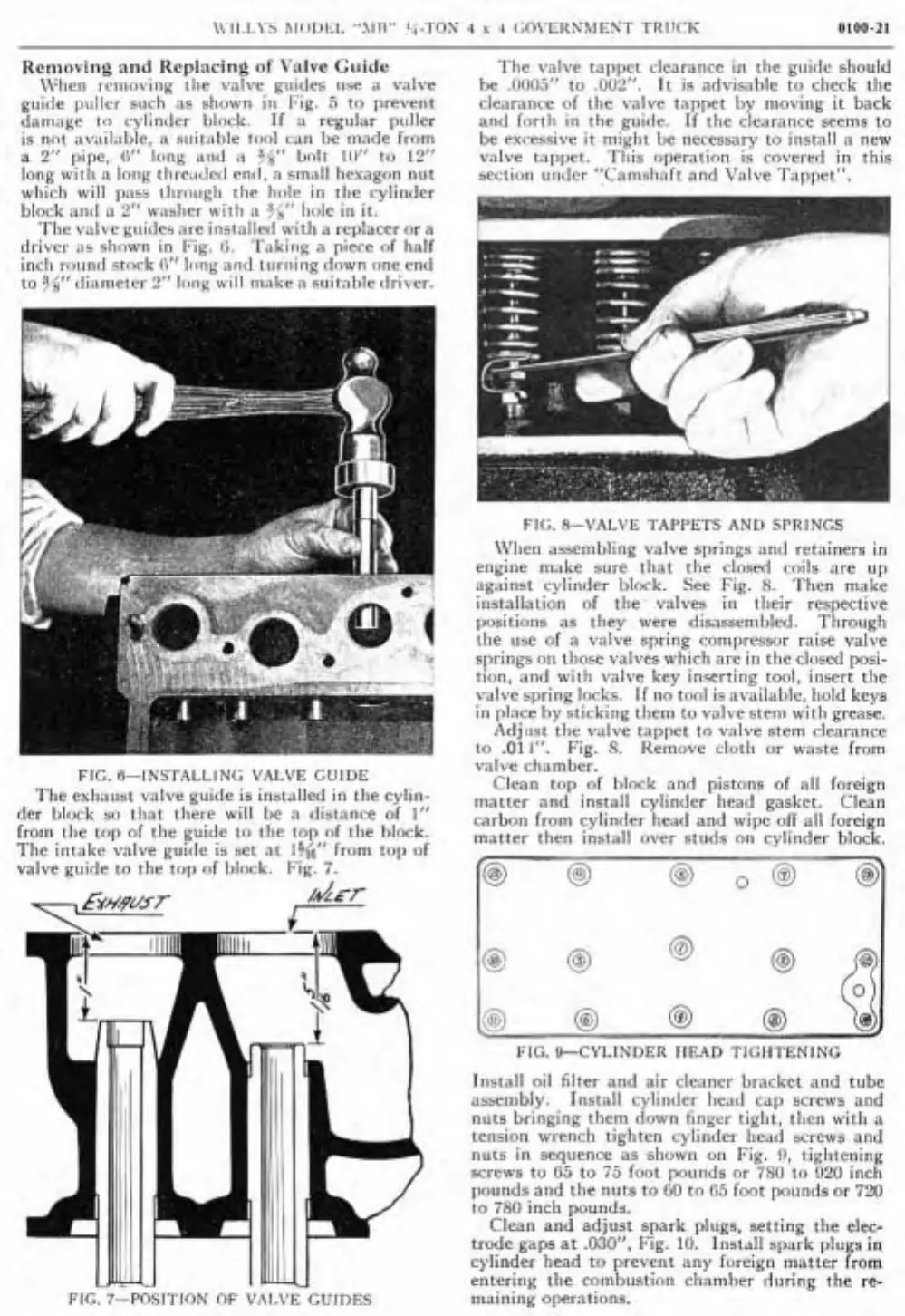
FIG.
R-INSI'ALLING
VAI.VE
(;UIDE
The exhaust valve guide is iris[iilled in tlie cyliii-
der block so tliat tliere wil1 bc a <listance of
1"
from tlie top of tlie guide to tlie top of tlie hlock.
Tlie intake valve guiile is set at
14(6"
from tol) of
valve guide to the
top of block. Fig.
7.
FIG. 7-POSITION OF VAI.VE GUIDES
ï'lie vslve tappet clearance in tlie guide should
he .000.5" to ,002". It
is
advisable to check tlie
clearaiice of the valve tappet by moving it back
and
fortli in the guide. If the clearance seems to
be excessive
it might be necessary to install a new
valve
tappet. Tliis operation is covered in this
sectioii
uiider 'ICaiiisliaft and Valve Tappet".
Fl(;. .S-\'AL\lE 'ïAPPE1'S
ANU
SPRINGS
Wlien assembliiig valve springs ;incl retainers in
engine make sure tliat tlie
closed coils are up
against cylinder block. See
Fig.
8.
Then make
installation of the valves in
tlieir respective
positions as they were disassembled. Througli
the iise of a valve spring compressor raise valve
springs on
tliose valves wliich are in the closed posi-
tion, and with valve key inserting tool, insert the
valve
spring locks. If no ton1
is
available, hold keys
in
place by sticking them to valve steni witli grease.
Adjiist the valve tappet to valve stem clearance
to
.01
1".
Fig.
8.
Kemove clotli ar waste from
valve
chamber.
Clean top of block and pistons of al1 foreign
matter and install cylinder liead
gasket.
Clean
carbon from cylinder
head and wipe olT al1 foreign
matter then install over studs on cylinder block.
FIG.
9-CYLINDER IIEAD TIGHTENLNG
Iiistall oil filter and air cleaner bracket and tube
assenibly. Install cylincler Iieacl cap screws and
nuts
bringing them down finger tiglit, tlien witli a
tensioii wrench tighten cylinder head screws and
nuts in seqiience as shown on Fig.
!l, tightening
screws to
G5
to
75
foot pounds or 780 to 020 inch
pounds and the nuts to
GO
to
G5
foot pounds or 720
to 780 inch pounds.
Clean and adjust spark plugs, setting the
elec-
trode gaps at .0301', Fig. 10. Install spark plugs
in
cylinder liead to prevent any foreign matter from
entering the combustion
cliamber rluring the re-
maining operations.
 Loading...
