WILLYS
MODEL "MB" K-TON
4
x
4
COVERNMENT TRUCK
0100-23
Camshaft and Valve Tappets
The alloy cast steel camshaft Fig.
11
rotates on
four
bearings whicli are lubricated under oil pres-
sure through drilled passages in the crankcase. The
front bearing carries the thrust and is a steel back
babbitt-lined
shell. This bearing is staked in place
to
prevent rotation and endwise movement. See
Fig.
12.
The valve tappets are luhricated througli oil
troughs cast in crankcase and drilled passages to
valve
tappet guides. The oil troughs are filled
from oil spray Iioles
at
connecting rod bearing
ends.
A
groove cut in center of valve tappet
shank carries tlie oil up and down
iii
guides.
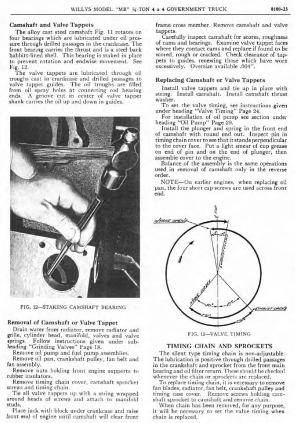
FIG.
12-STAKING CAMSHAFT BEARING
Removal
of
Carnshaft
or
Valve Tappet
Drain water from radiator, remove radiator and
grille.
cylinder head. manifold. valves and valve
iiprings.
Fo!low instructions given under sub-
heading "Grinding Valves" Pape
18.
Remove oil pump and fuel
assemblies.
Remove oil pan. crankshaft ~ullev. fan belt and
,
.
lan assembly.
.
Remove nuts holding front engine supports to
rubber
insulators.
Remove timing chain cover. camshaft sprocket
screws and timing chain.
Tie
al1 valve tnppets up with
a
string wrapped
around heads of screws and attach to manifold
studs.
Place jack
witli block under crankcase and raise
front end of engine until camshaft
wil1 clear front
frame cross
member. Remove camshaft and valve
tappets.
Carefully inspect camshaft for scores, roughness
of cams and bearings. Examine valve tappet faces
where they contact cams and replace
if
found to be
scored,
rough or cracked. Check clearance of
tap-
pets to guides, renewing those which have worn
excessively. Oversize available
.004".
Replaclng Camshaft
or
Valve Tappets
Install valve tappets and tie up in place with
string. Install camshaft. Install camshaft thrust
washer.
To set the valve timing, see instructions given
under heading "Valve Timing" Page
24.
For installation of oil pump see section under
heading
"Oil Pump" Page
29.
Install tlie plunger and spring in the front end
of camshaft with round end out. Inspect pin in
timingchain cover tosee that it
standsperpendicular
to the cover face. Put
a
light smear of cup grease
on end of pin and on the end of plunger, then
assemble cover to the engine.
Balance of the assembly is the
Same operations
used in removal of camshaft only in the
reverse
order.
NOTE-On earlier engines. when replacing oil
pan, the four short cap screws are used across front
end.
FIG.
13-VALVE TIMING
TIMING CHAIN
AND
SPROCKETS
The
silent type timing chain is non-adjustable.
The lubrication is positive through
drilled passages
in the crankshaft and sprocket from the front
main
bearingand oil rilterreturn.l'liese slioulrl hecheckccl
whenever tlie chain or sprockets are replaceù.
To replace timing chain,
it
is necessary to remove
fan blades. radiator. fan belt, crankshaft pulley and
timing case cover. Rernove screws
Iiolding cam-
shaft sprocket to camsliaft and remove clinin.
Wheri cliain lias been removed, for any purpose,
it wil1 be necessary to set tlie valve timing when
chain is
replaced.
 Loading...
