ASSEMBLING CONNECTING ROI>
T0
PISTON
Clamp connecting rocl in vise usiiig vise jaw
protector shiel<ls of n soft nietal or two pieces of
hardwood on eacli side of connecting rd three
inches Iroin piston pin end.
Start piston pin
iii
piston with groove facing
down.
Assemhle pistoii to connecting rad with the
slot in piston, No.
2.
Fig.
29
opposite oil spray hole
in bearirig end
of
connecting
rad,
No.
1.
Install
piston pin clariip screw.
Center
piston o11 pin and place asseriiI)ly oii
connecting
rocl aligiiiiig íixture. Tilt pistori to left
witli piston resting apaiiist siirface plate. \Villi
feeler gauge measiire clearance between piston skirt
an<l surface plate. See 'ig.
30.
Tilt piston to riglit
and check clearance. See Fig.
32.
11 clearance is
within
.OOR"
oii hr~ili left and riglit positions con-
necting rol1
is
in
;ilignment.
A
difference Kreater
tlia~i
.003"
inclicates connertinc rol1
is
turistrrl.
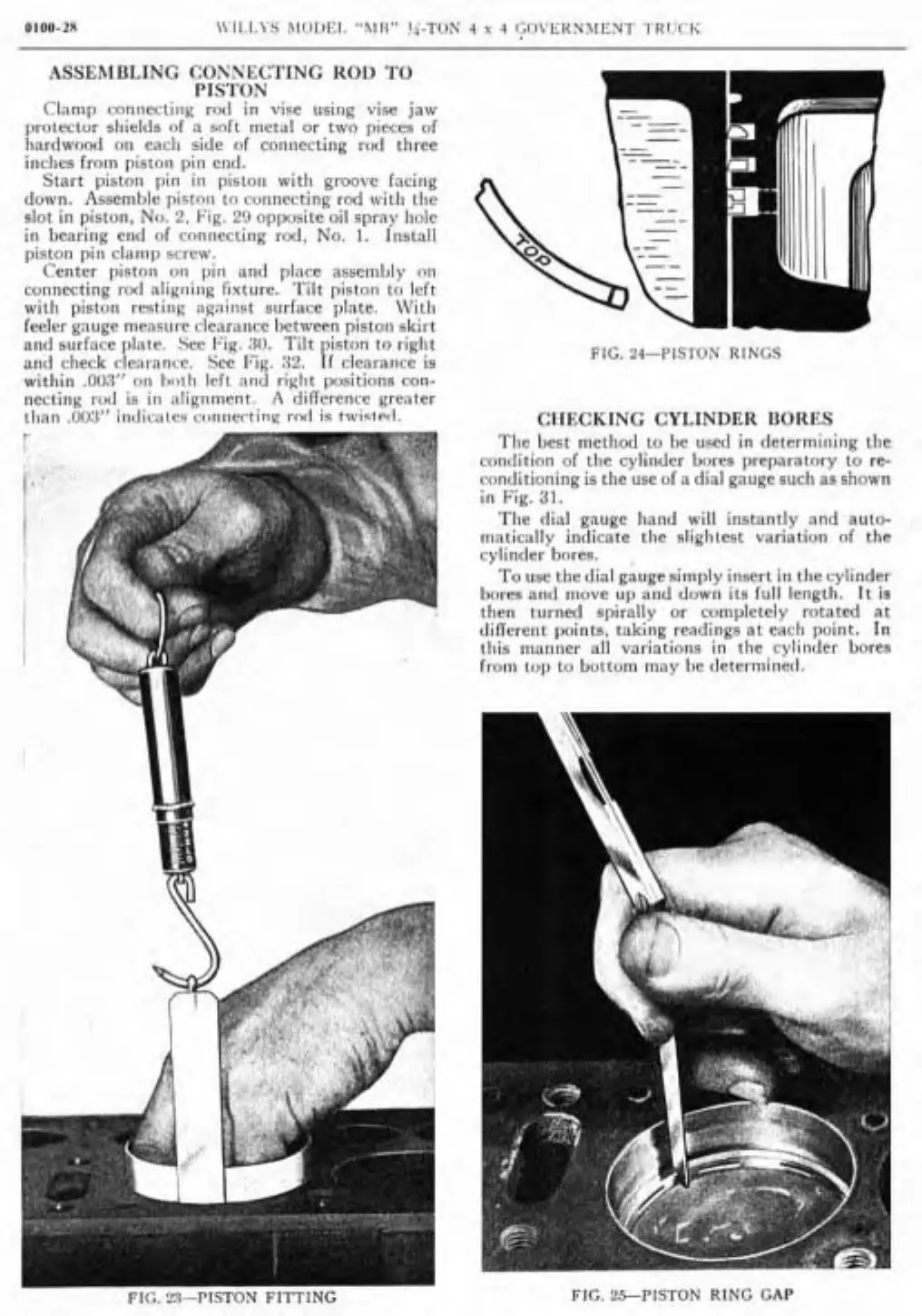
FIG.
24-PIS-TOS
RlKGS
CHECKING CYLINDER UORES
The best method to be used in lleterininiiig tlie
con~lition of tlie cylinder bores preparatory to re-
ronditioning
is
tlie use of a dial gauge sucli as shown
in Fig.
31.
The dial gauge hand wil1 instantly and auto-
niatically indicate tlie sliglitest variation of tlie
cylincler bores.
,
To use the dial gauge simply insert in the cylinder
bores and move up and down its
full length. It is
then turned
spirally or completely rotated at
dillerent points, taking readings at each point. In
iliis manner al1 variations in tlie cylinder bores
frorii top
10 bottom may he determiiie<l.
FIG.
ZSPISI'ON RING
GAP
 Loading...
