'i'lie oil piiiiip
is
driven from
a
spiral gear on the
carnsliaft \vliicli is located at tliecenter of the engine
blnck oii lelt Iiarid side. See No.
22,
Fig.
1.
To reinove
oil
piriiip from engine for disniaiitling;
reniove tlie tliree nuts on studs holcling oil piiiiip
to crankcase. Slide oil piinip from studs. lieiiiove
screw No.
(i,
Fig.
34.
in oil puiiip cover [>late wliicli
wil1 alluw cover to be reiiio\~ed from linusing.
'TU reiiiove ilriveii gear No.
16,
file
111f
one eiid
of straight
pin No.
17,
witli a smal1 drift. drive piii
tliroiigli tlie sliaft.
'L'lie
oil
piiriip shaft ani1 rotor
No.
12
rnii
lx
reinoved from the body
iii
ai1 ;issein-
bly.
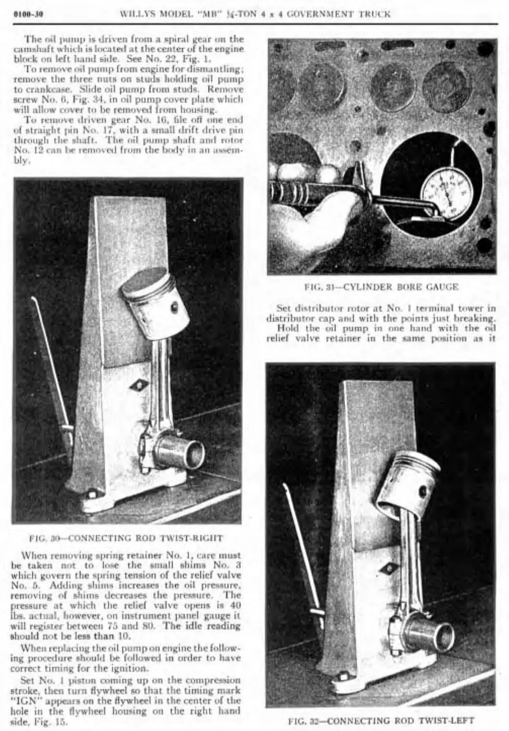
1:Ii;.
3i+CONNECTINC
Rol>
T\ïIST-RI<;IIT
Wlien removirig spring retainer No.
1.
care must
be taken not to
lose tlie sniall sbims No.
3
wliicli govern the spring tensioii of tlie relief valve
No.
5.
Addirig sliims increases the oil pressiire,
removing of sliiiiis decreases tlie pressure.
Tlie
pressure nt whicli tlie relief valve opens is
40
Ibs. actiial, Iiowever, on instrument panel gauge it
wil1 register between
i5
and
SO.
Tlie idle reading
should not be
less tlian
10.
Wlieii replacing tlieoil puinpoii eiigine the follow-
ing procedure should be followed in order to Iiave
correct timing for tlie
ignition.
Set No.
I
piston coming up on the coinpression
stroke, then
turn flywheel so that tlie timing niark
"IGN" appears on the flywheel
iii
tlie center of tlie
hole in tlie
flvwheel housine oii tlie rielit Iiancl
Set distribiilor rotor at No.
I
terniinal trnver in
distrilmtor cap atid nith tlie points jiist breaking.
Hold the uil pump in one hatid witli tlie
oil
relief valve retainer in tlie Same position
as
it
"
side.
Fig.
15.
FIG.
31-CONNECTING
ROD
T\I'IST-LEFT
 Loading...
