0300-44
5VII.LYS
MODEL
"MB"
%-TON
4
x
4
GOVERNIIIENT TICUCK
Wlien tlie idle speed position of tlie throttle is
fixed at an idle speed of
8
miles per hour, it leaves
enough
of tlie slotted port as reserve to cover tlie
range in speed
between idle and tlie time wlien tlie
high speed system begins to cut in.
Tlie idle
a<ljiistiiig screw No.
13
varies tlie
quantity of tlie idle
mixttire.
IIigli Speed Circuit
Tlie
liigli speed circiiit, Fig.
5
cuts in as the
tlirottle is opened wicle enougli lor
a
speed of a
little more tlian
20
miles per liour. The velocity
of the air flowing down tlirough the carburetor
throat creates a
pressure sligbtly less tlian atmos-
plieric pressure at tlie tip of tlie main iinzzle,
No.
20.
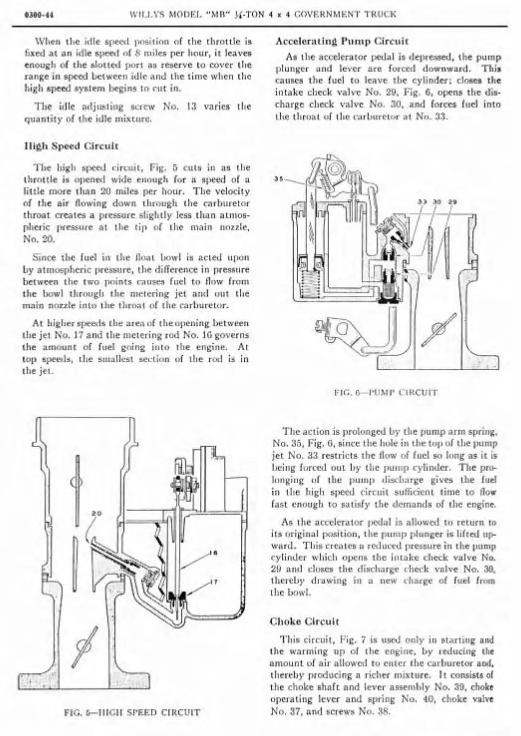
Accelerating Pump Circuit
As tlie accelerator
peda1 is depressed, the pump
plunger and lever are forced downward. This
causes the fuel to leave tlie cylinder;
closes the
intake check valve No.
29,
Fig.
6,
opens tlie dis-
charge check valve No.
30,
and forces fiiel into
the tliroat of tlie carburetor
at
No.
33.
Since tlie fuel
iii
tlie float bowl is acted upon
by atmosplieric
pressure, tlie
differente
in pressiire
between the two points causes fuel to flow from
tlie bowl
tlirougli tlie metering jet and out tlie
main nozzle into tlie tliroat of tlie carburetor.
At
Iiiglier speeds tlie areaof tlieopening between
tlie jet No.
17
and tlie metering rod No.
10
governs
the amount of fuel going iiito tlie engine. At
top speeds, tlie
siiiallest section of tlie rod is in
tlie jet.
FIG. G-PUMP CIRCUIT
FIG.
&-HIGH
SPEED
CIRCUIT
The
action is proloiiged by tlie pump arm spring,
No.
35,
Fig.
G,
since tlie hole in the top of tlie pump
jet No.
33
restricts the flow of fuel so long as it is
Iieing forced out by tlie puiiip cyliiider. Tlie pro-
longing of the puin{> discliarge gives the fuel
in tlie high speed circuit
suficicnt tinie to flaw
last enough to satisfy the demands of tlie engine.
As tlie accelerator
liedal is allowed to return to
its original position, tlie punip plunger is lifted iip-
ward. Tliis creates a reduced pressure in tlie pump
cylinder which opens the
intake check valve
No.
29
and closes tlie discliarge check valve No.
30,
tliereby drawing
i11
a new charge of fuel from
tlie bowl.
Clioke
Circuit
'ïliis circuit, Fig.
7
is iised only in starting and
tlie warming up of the engiiie,
by
reducing
the
amount of air allowed to enter the carburetor and,
tliereby producing a richer
iiiixture. It consists
of
the choke shaft and lever assembly No.
39,
choke
operating lever and spring No.
40,
clioke valve
No.
37,
and screws No.
38.