WILLYS MODEL
"MB"
M-TON
4
x
4
GOVERNMENT TRUCK
0300-45
Low
Speed Circuit
FIG.
7-CHOKE CIRCUIT
SERVICING
AND ADJUSTMENT
Float Circuit
The Float Circuit is
illustrated in Fig.
3.
If
float
is
loaded witli fuel or damaged, or
if
the holes for the pin are worn, the carburetor
wil1 flood. Poor action of float needle results
if
the lip of the float bracket is worn. In this event.
it should be smoothed with emery cloth.
The needle and seat may leak
because of wear,
damage or sticking and wil1 cause the carburetor
to flood. Needles and seats are
available only
in matched sets. Never replace the needle without
replacing tlie seat.
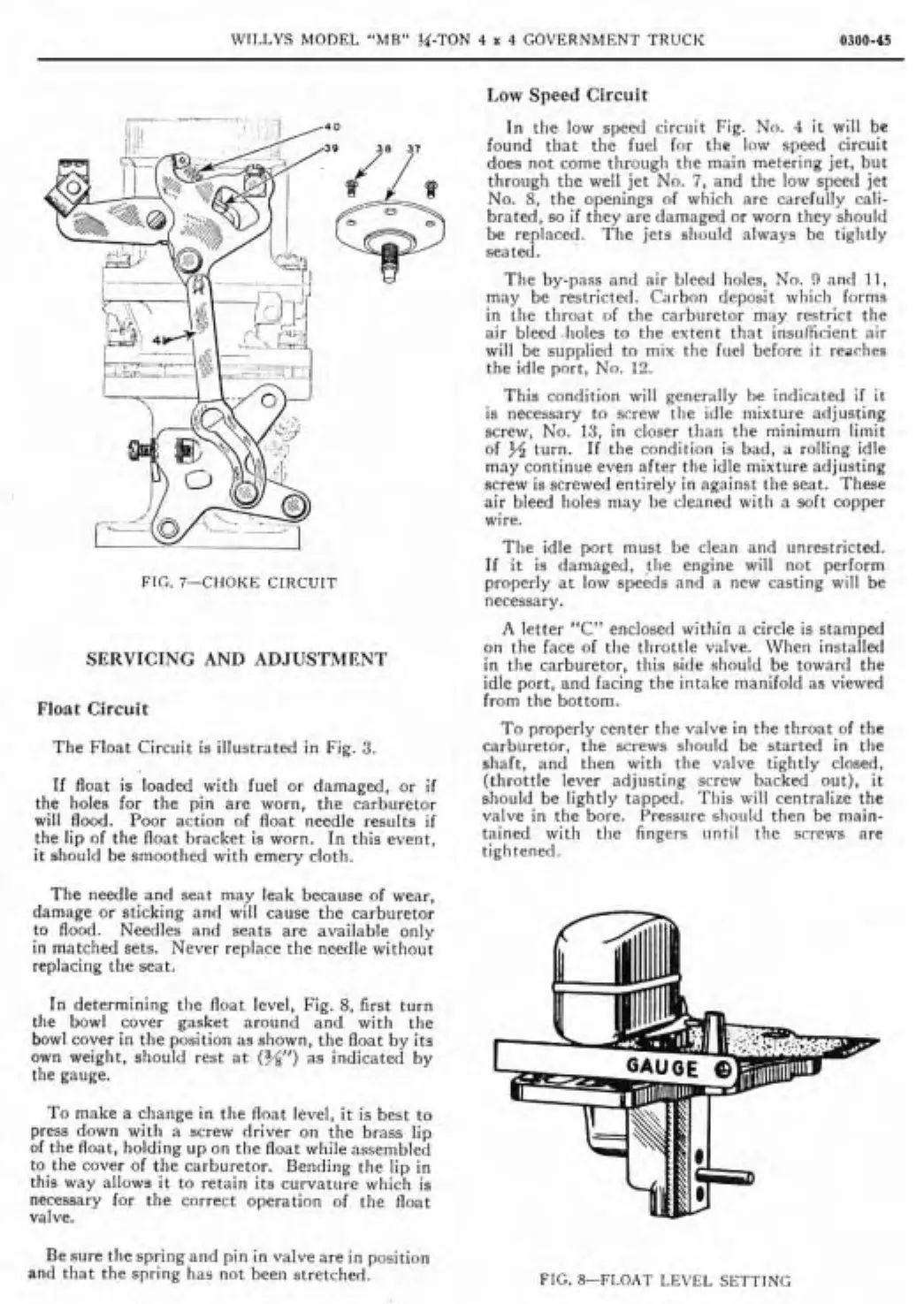
In determining tlie float level, Fig.
8,
first turn
the bowl cover
gasket around and with the
bowl cover in the position as
shown. the float by its
own weight. should rest at
(w)
as
indicated by
the gauge.
To make a change in the float level, it is best to
press down with
a
screw driver on the brass lip
of the float, holding up on tlie float while assembled
to the cover of the carburetor.
Bending the lip in
this way
allows it to retain its curvature which is
necessary for the correct operation of tlie float
valve.
In tlie low speed circuit Fig. No.
4
it will
be
found that the fuel for the low speed circuit
does not
come througli the main metering jet, but
through the
wel1 jet No.
7,
and the low speed jet
No.
S,
the openings of whicli are carefully cali-
brated. so
if
they are damaged or worn they should
be
replaced. The jets slioiild alxvays be tightly
seateù.
The by-pass and air bleed
holes, No.
9
nnd 11,
may be restricted. Carbon deposit which forms
in tlie throat of the carburetor may restrict the
air
bleec.lioles to the extent that insulficient air
wil1 be supplied to mix the fuel before
it
reaches
the idle port, No.
12.
This condition wil1 generally be indicated
if
it
is
necessary to screw tlie idle niixture adjusting
screw, No.
13.
in closer tlian the minimum limit
of turn. If the condition is bad, a rolling idle
may continue even
after the idle mixture adjusting
screw is screwed entirely in against the seat. These
air bleed holes may be cleaned
witli a soft copper
wire.
The idle port must be clean and
unrestricted.
If
it
is damaged, tlie engine wil1 not perform
properly at
low speeds nnd a new casting wil1 be
necessary.
A
letter
"C"
enclosed within a circle is stamped
on tlie face of the tlirottle valve. When
installed
in tlie carburetor, this side should be toward the
idle port, and facing the intake manifold as viewed
from the
bottom.
To properly center the valve in the throat of the
carburetor. the screws slioiild be started in tlie
shaft, and then with the valve tightly
closed.
(throttle lever adjusting screw backed out), it
sliould be lightly tapped. This will centralize the
valve in the bore.
Press~ire sliould then be main-
tained with the fingers iintil the screws are
tiglitened.
Besure thespringand pin in valveare in position
and that the
spring has nor been stretchml.
FIG. &FLOAT
LEVEL
SETTING