Do you have a question about the Wilo Control Booster CC and is the answer not in the manual?
Provides overview of the manual's language, purpose, and availability.
Explains safety symbols, signal words, and their meaning.
Details required qualifications for installation, operation, and maintenance personnel.
Covers operator and installation safety, risks of non-compliance, and improper use.
Discusses safety implications of unauthorized changes and spare parts.
Details precautions for safe transport and storage to prevent damage.
Describes the intended use of the CC switchgear for pressure-boosting systems.
Details the meaning of characters in the product's type designation.
Presents key technical specifications such as voltage, frequency, and protection class.
Lists the items included with the CC-Booster switchgear.
Lists optional accessories that can be ordered separately.
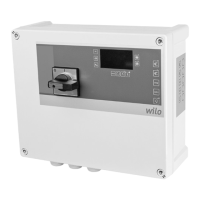
Provides a detailed description of the CC switchgear and its components.
Introduces the overall function and operational aspects of the switchgear.
Details the motor protection mechanisms, including excess temperature and current.
Provides instructions for physical installation, including wall and floor mounting.
Details the steps and safety precautions for electrical connections.
Explains factory pre-sets and how they can be restored by service.
Describes how to verify the correct direction of motor rotation.
Details the adjustment of motor protection settings.
Covers installation instructions for optional modules and transmitters.
Specifies that maintenance and repair must be done by qualified personnel.
Explains how faults are displayed, signaled, and acknowledged.
Describes the system's memory for storing and reviewing past faults.
Defines the data types used in the ModBus communication protocol.
Provides a detailed list of ModBus parameters and their properties.
| Max. ambient temperature | 40 °C |
|---|---|
| Protection class | IP54 |
| Housing material | Plastic |
| Ambient temperature | 0 °C to +40 °C |
| Storage temperature | -20 °C to +60 °C |
| Relative humidity | 95% (non-condensing) |