en
36 Installation and operating instructions • Wilo-Control EC-L • Ed.04/2022-09
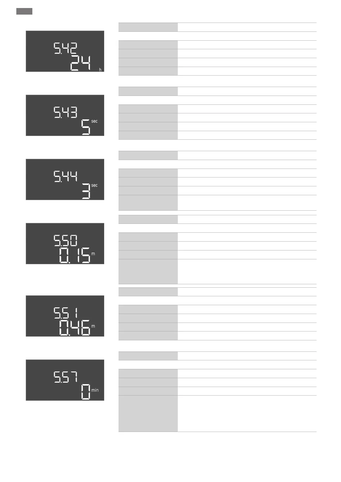
Fig.40: Menu 5.42
Menu no. 5.42
Software version: All
Description “Pump kick interval”
Value range 1…336h
Factory setting 24h
Explanation Time after which a pump kick takes place.
Fig.41: Menu 5.43
Menu no. 5.43
Software version: All
Description “Pump kick duration”
Value range 0…60s
Factory setting 5s
Explanation How long a pump kick runs for a pump.
Fig.42: Menu 5.44
Menu no. 5.44
Software version: All
Description Activation delay after power failure
Value range 0…180s
Factory setting 3s
Explanation Time until the switchgear automatically restarts after a power
outage.
Fig.43: Menu 5.50
Menu no. 5.50
Software version: All
Description Dry-running level (drain)/ min. water level (fill)
Value range 0...12.5m
Factory setting 0.15m
Explanation Enter fill level.
If the level is monitored with a separate float switch, deactiv-
ate the level sensor: Enter the value “0.00m”.
Fig.44: Menu 5.51
Menu no. 5.51
Software version: All
Description High water level
Value range 0...12.5m
Factory setting 0.46m
Explanation Enter fill level.
Fig.45: Menu 5.57
Menu no. 5.57
Software version: All
Description Max. running time per pump
Value range 0…60min
Factory setting 0min
Explanation Maximum permissible running time of a pump. Once the time
has been exceeded, the system switches to the next pump.
After three change cycles, the collective fault signal (SSM) is
activated.
The setting “0min” switches the running time monitoring off.
 Loading...


