en
Installation and operating instructions • Wilo-Control EC-L • Ed.04/2022-09 37
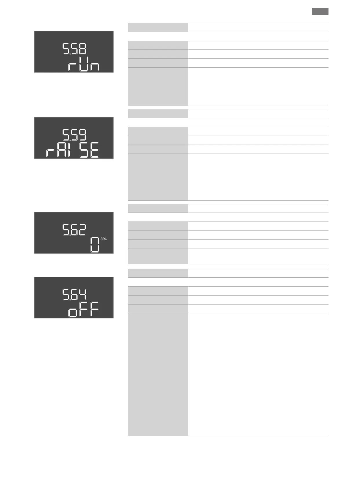
Fig.46: Menu 5.58
Menu no. 5.58
Software version: All
Description Collective run signal (SBM) function
Value range on, run
Factory setting run
Explanation A run signal for the switchgear or attached pump can sent via a
separate output:
• “on”: Switchgear ready for operation
• “run”: At least one pump is running.
Fig.47: Menu 5.59
Menu no. 5.59
Software version: All
Description Collective fault signal (SSM) function
Value range fall, raise
Factory setting raise
Explanation In case of an error, a general fault message can be sent via a
separate output:
• “fall”: The relay drops out.
Optionally, this function can be used for controlling the
mains voltage supply.
• “raise”: The relay picks up.
Fig.48: Menu 5.62
Menu no. 5.62
Software version: All
Description Dry-running protection delay
Value range 0…180s
Factory setting 0s
Explanation Time until the pump are deactivated after reaching the dry run
level.
Fig.49: Menu 5.64
Menu no. 5.64
Software version: All
Description Ex-mode On/Off (only available in the “drain” operating mode!)
Value range on, off
Factory setting off
Explanation The following functions are adjusted when the Ex-mode is ac-
tivated (on):
• Follow-up times
All follow-up times are ignored and the pumps switched off
immediately!
• Dry-running level (by level sensor or dynamic pressure bell)
The following actions are only possible once the “All pumps
off” fill level has been exceeded:
– Reactivation of the pumps
– Resetting the error message
• Alarm dry-running protection (via float switch)
Alarm manual reset (anti-reactivation lock)!
• Alarm thermal motor monitoring
Alarm manual reset (anti-reactivation lock)!
Observe the additional requirements in the chapter on explos-
ive atmospheres in the appendix!
 Loading...


