ENGLISH
5.2 Electrical Wiring
All electrical site works to be carried out by qualified and
locally licenced electricians strictly in accordance with locally
ruling regulations.
● Check available power supply,
● take note of pump name plate data requirements,
● power wiring 3 x 1.5 mm". (Minimum cable size 6 mm, maximum 9 mm
OD).
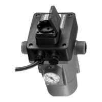
● To ensure water tightness and pull-force relief from the cable glands the
power
cable must be of sufficient outside diameter (e.g. 05 VV-F 3 (7) G 1,5
oder AVMH-I 3 (7) x 1,5).
● All electrical wiring to be executed according to Fig.4.
● Supply side fuse: see as for pump; maximum however 10 A, inert.
● Strictly adhere to local earthing regulations.
● If required (see VDE 0100), a ground fault circuit interruptor (GFCI)switch
must be provided and installed by others.
6 Commissioning
For possibly required prestart and commissioning procedures for the pump
refer to the separate installation and Operating Instruction for the pump.
Before initial start-up it must be ensured that sufficient suction capability is
available and that the pump is primed and filled.
On initial start-up the pump will run for 8 seconds, after that a renewed start-up
can be effected by keeping the reset button pushed.
7 Maintenance
Warning!
Electrical Shock Hazard!
Prior to maintenance or repair work turn off the pump and
ensure that it is not turned on by unauthorised personnel.
16 (55)