Product description en
Installation and operating instructions Wilo-Padus UNI 9
CAUTION
Use in biogas applications forbidden!
The fluids in biogas applications are highly aggressive.
These fluids will destroy the pump. Use with these
fluids is strictly forbidden!
The submersible pumps must not be used for pumping of:
ƒ Untreated sewage
ƒ Sewage containing faeces (as per EN12050-1)
ƒ Drinking water
ƒ Fluids containing hard components (such as stones, wood,
metal, etc.)
ƒ Fluids containing high quantities of abrasive contents (e.g.
sand, gravel).
Intended use requires compliance with this manual. Any other use
is regarded as non-compliant with the intended use.
4 Product description
4.1 Design
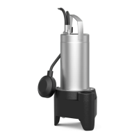
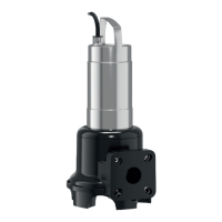
Submersible drainage pump as a submersible monobloc unit for
intermittent operation for wet well installation.
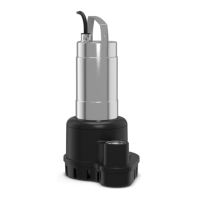
Fig.1: Overview
1 Handle/attachment point
2 Motor housing
3 Hydraulics housing
4 Pressure port
5 Strainer
6 Connection cable
4.1.1 Hydraulics
Centrifugal hydraulics with open, multi-channel impeller and ver-
tical threaded connection on the pressure side. The hydraulics are
not self-priming, in other words, the fluid must flow in either au-
tomatically or with supply pressure.
4.1.2 Motor
The drive versions used are single-phase current and three-phase
current surface-cooled motors. The motor is cooled by the fluid
around it. The waste heat is transferred directly to the fluid via the
motor housing. The motor may emerge during operation.
With single-phase current motors, the operating capacitor is in-
tegrated in the motor. The connection cable is available in the fol-
lowing versions:
ƒ Single-phase current version:
– With shockproof plug
– With shockproof plug and fitted with a float switch
ƒ Three-phase current version:
– With bare cable end
– With CEE plug and fitted with a float switch
4.1.3 Seal
The seal for the fluid and the motor compartment is made via two
mechanical seals. The sealing chamber between the mechanical
seals is filled with medical white oil.
4.1.4 Material
ƒ Pump housing: PP-GF30
ƒ Impeller: PP-GF30
ƒ Motor housing: 1.4301 (AISI304)
ƒ Shaft: 1.4401 (AISI316)
ƒ Seal on the fluid side: SiC/SiC
ƒ Seal on the motor side: C/Cr
ƒ Static seal: NBR (nitrile)
NOTICE!In material version “B”, all parts that come in contact
with the fluid are made of stainless steel 1.4401 (AISI316).
4.1.5 Fitted accessories
Float switch
In the “A” and “VA”version, the pump is equipped with a float
switch. Depending on the fill level, it is possible to switch the
pump on and off automatically using the float switch.
Plug
In the “P” and “A” version, a shockproof plug is attached for
single-phase AC motors and a CEE plug is attached for three-
phase current motors. The plug is designed for use in commer-
cially available shock-proof or CEE sockets and is not overflow-
proof.