Do you have a question about the Wilo Para STG and is the answer not in the manual?
Read installation and operating instructions before work and keep them accessible.
Safety instructions for preventing personal injury and property damage, displayed with signal words/symbols.
Defines signal words like DANGER!, WARNING!, CAUTION!, NOTICE for hazard communication.
Explains symbols used for electrical voltage, general danger, hot surfaces, magnetic fields, and notices.
Personnel must be instructed on regulations and have read instructions. Electrical work requires a qualified electrician.
Specifies requirements for electrical work, including disconnection, RCDs, earthing, and qualified personnel.
Operator responsibilities include qualified personnel, on-site guards, and replacing defective parts.
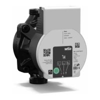
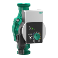
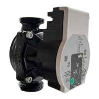
Provides a numbered overview of the Wilo-Para pump's parts, referencing Figure 1.
Describes the high-efficiency circulator for hot-water heating systems with differential pressure control.
Explains the coding system used in model designations for Wilo-Para pumps.
Details electrical connection voltage, protection class (IPX4D), and energy efficiency index (EEI).
Specifies fluid temperatures, operating pressure, inlet pressure, and LED indicator meanings.
Explains the function of LED indicators for signal display, control mode, and pump curve selection.
How to press the button to select control mode and pump curve.
How to press and hold the button for venting, restart, and lock/unlock functions.
Describes external control using a PWM signal for pump speed adjustment.
Pump speed controlled by PWM input signal in iPWM 1 mode for heating and geothermal applications.
Pump speed controlled by PWM input signal in iPWM 2 mode for solar applications.
Maintains constant delivery head irrespective of flow; recommended for underfloor heating.
Maintains constant volume flow in fixed speed stages; recommended for fixed system resistance.
Activating the pump venting function to remove air from the system.
Initiating manual restart or locking/unlocking the operating button.
Restoring the pump to its factory default settings.
Circulators are intended for hot-water heating systems and similar systems with changing volume flows.
Lists permitted fluids like heating water and water-glycol mixtures, with usage conditions.
Any use beyond intended use is considered misuse and voids warranty claims.
WARNING: Danger of injury or material damage from improper use of the pump.
Lists items included in delivery and available accessories for the pump.
Instructions for checking for damage upon delivery and conditions for transport/storage.
Installation must be by qualified technicians; includes warnings about hot surfaces and fluids.
Guidance on preparing for installation, including indoor and outdoor scenarios.
Warning about potential burns from touching hot pump housing and motor surfaces.
Warning about the risk of scalding from hot fluids during pump installation or removal.
Caution: Incorrect installation position may damage the pump; observe permissible positions.
Caution: Leaking water may damage the control module; align shut-off devices carefully.
Key points for installing the pump, including direction arrow, horizontal motor, and connections.
Caution: Insufficient heat dissipation may damage the control module and motor.
WARNING: Risk of fatal injury from magnetic field for people with medical implants.
Electrical connection must be by a qualified electrician.
DANGER: Risk of fatal injury from electrical voltage if live components are touched.
Caution: Pulsed mains voltage can damage electronic components; use sinusoidal AC voltage.
Corresponds voltage/current to rating plate, specifies fuse, and mandates sinusoidal AC voltage.
Instructions for connecting the mains cable, including standard/optional types and cable assignment.
Steps for installing the Wilo-Connector, including power disconnection and terminal assignment.
Earth the pump and connect the Wilo-Connector until it snaps into place.
Procedure for safely disconnecting the Wilo-Connector using a screwdriver.
Connecting to existing pump cables or the iPWM signal cable.
Steps for filling and venting the system, including automatic and manual pump venting.
CAUTION: Connecting mains voltage to iPWM pins will destroy the product.
How to select control modes and pump curves using the operating button and LED display.
Table showing LED display indicators for different control modes and pump curves.
Activating/deactivating the key lock for the operating button to prevent unauthorized changes.
NOTICE: All settings and displays are retained if the power supply is interrupted.
Restoring the pump to its factory default settings by pressing the button while switching off.
Procedure for safely shutting down the pump, especially if components are damaged.
Guidelines for cleaning the pump using a dry duster and avoiding liquids or aggressive agents.
Troubleshooting guide for common faults, their causes, and recommended remedies.
The fault signal LED indicates faults; the pump switches off and attempts cyclical restart.
Faults indicated by a solid red LED: Blocking, Contacting/winding, Under/overvoltage, Module temp, Short-circuit, Gen. op.
Faults indicated by flashing red/green LED: Dry run, Overload.
Pump attempts automatic restart; manual restart initiated via button press.
Notice regarding LED display after restart and contacting service if fault persists.
Proper disposal and recycling of electrical/electronic products to prevent environmental damage.
NOTICE: Disposal in domestic waste is forbidden for electrical and electronic products in the EU.
Declaration by the manufacturer stating compliance with relevant EU directives for the product series.
Lists Wilo subsidiaries globally with addresses, phone numbers, and email contacts.
| Brand | Wilo |
|---|---|
| Model | Para STG |
| Category | Water Pump |
| Language | English |