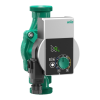
Installation and operating instructions Wilo-Para STG 33
en
Operating button
Press
•Select control mode
• Select pump curve (I, II, III or iPWM 1, iPWM 2) within
the control mode
Press and hold
• Activate the pump venting function
(press for 3 seconds)
• Activate manual restart (press for 5 seconds)
• Lock/unlock button (press for 8 seconds)
3.1 Control modes and functions
External control
via iPWM signal
The required setpoint/actual value comparison for con
-
trol is performed by an external controller.
A PWM signal (pulse-width modulation) is fed as a cor
-
recting variable to the pump.
The PWM signal generator gives the pump a periodic
sequence of impulses (the duty cycle) in accordance
with DIN IEC 60469-1.
iPWM 1 mode (Heating and geothermal):
In iPWM 1 mode, the pump speed is controlled according
to the PWM input signal.
Behaviour in the event of a cable break:
If the signal cable is disconnected from the pump, e.g.
due to a cable break, the pump accelerates to maximum
speed.
PWM signal input [%]
< 5: Pump runs at maximum speed
5-85: The speed of the pump decreases linearly
from n
max
to n
min
85-93: Pump runs at minimum speed (operation)
iPWM 2
iPWM 1
55 (45)%
45 (55)%
5 (95)%
65 (35)%
35 (65)%
75 (25)%
85 (15)%
15 (85)%
25 (75)%
H/m
Q/m³/ h
% iPWM 1 (% iPWM 2)
max
n
¹/min
min
0 5 85 88
93 100
PWM
%