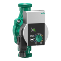
Installation and operating instructions Wilo-Para STG 41
en
Connecting the pump
• Earth the pump.
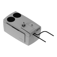
• Connect the Wilo-Connector to the connection
cable until it snaps into place (Fig. 5f).
Removing the Wilo-Connector
• Disconnect the connecting cable from the power
supply.
• Remove the Wilo-Connector using a suitable
screwdriver (Fig. 6).
Connection to an
existing device
The pump can be directly connected to an existing pump
cable with a 3-pin plug (e.g. Molex) when being replaced
(Fig. 3, item a).
• Disconnect the connecting cable from the
power supply.
• Press down the locking button of the installed plug
and remove the plug from the control module.
• Observe the terminal assignment (PE, N, L).
• Connect the existing device plug to the plug
connection (12) of the control module.
iPWM
connection
Connecting the iPWM signal cable (accessories)
• Connect the signal cable plug to the iPWM
connection (11) until it snaps into place.
iPWM:
• Cable assignment:
1 brown: PWM input (from controller)
2 blue or grey: Signal earth (GND)
3 black: PWM output (from the pump)
•Signal properties:
- Signal frequency: 100 Hz – 5000 Hz
(1000 Hz nominal)
- Signal amplitude: Min. 3.6 V at 3 mA to 24 V
for 7.5 mA, absorbed by the pump interface.
- Signal polarity: yes