Product description en
Installation and operating instructions Wilo Motor T 17.3, 20.2:, EMU FA, Rexa SUPRA, Rexa SOLID 57
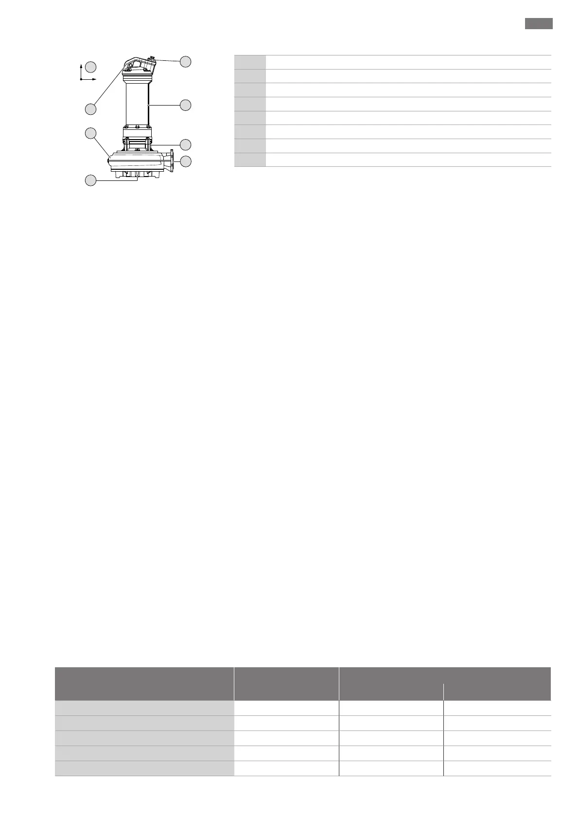
Fig.1: Sample illustration
1 Connection cable inlet
2 Motor
3 Sealing/bearing housing
4 Pressure port
5 Suction port
6 Hydraulics housing
7 Attachment point/handle
8 Coordinate system: Vibration sensor in Digital Data Interface
4.1.1 Hydraulics
Centrifugal hydraulics with different impeller shapes, horizontal flange connection on
the pressure side, casing and impeller wear rings.
The hydraulics are not self-priming, in other words, the fluid must flow in either auto-
matically or with supply pressure.
Impeller shapes
The individual impeller shapes depend on the size of the hydraulics and not every im-
peller shape is available for every hydraulic system. The following is an overview of the
different impeller shapes:
ƒ Vortex impeller
ƒ Single-channel impeller
ƒ Two-channel impeller
ƒ Three-channel impeller
ƒ Four-channel impeller
ƒ SOLID impellers, closed or half open
Casing and impeller wear rings (depending on the hydraulics)
The suction port and impeller are subjected to the most stress when pumping. In the
case of channel impellers, the gap between the impeller and the suction port is an im-
portant factor for constant efficiency. The larger the gap between the impeller and the
suction port, the higher the losses in the delivery rate. The efficiency decreases and the
danger of clogging increases. In order to ensure long and efficient operation of the hy-
draulics, an impeller wear ring and/or neck ring is installed depending on the impeller
and the hydraulics.
ƒ Impeller wear ring
The impeller wear ring is attached to the channel impellers and protects the incom-
ing flow edge of the impeller.
ƒ Neck ring
The neck ring is installed in the suction port of the hydraulics and protects the in-
coming flow edge in the centrifugal chamber.
If worn, customer service can simply replace both components.
4.1.2 Motor
Surface-cooling, asynchronous or permanent magnet motor as three-phase current
version. The motor is cooled by the fluid around it. The waste heat is transferred directly
to the fluid or the ambient air via the motor housing. The motor may emerge during op-
eration, dry well installation is possible. NOTICE!Output and activation times must be
adapted to prevent the motor from overheating in dry well installation! The connec-
tion cable has bare cable ends.
Motor fittings overview
Asynchronous motor Permanent magnet motor
T20.2 T17.3...-P T20.2...-P
Design type
Asynchronous Synchronous Synchronous
Max. efficiency category (based on IEC60034)
IE3 IE5 IE5
Operation with frequency converter
o ! (Wilo-EFC) ! (Wilo-EFC)
Digital Data Interface
o • •
Immersed operating mode
S1 S1 S1
 Loading...