Ex rating en
Installation and operating instructions Wilo Motor T 17.3, 20.2:, EMU FA, Rexa SUPRA, Rexa SOLID 95
FM approval
The pumps are suitable for operation in potentially explosive atmospheres:
ƒ Protection class: Explosionproof
ƒ Category: Class I, Division 1
Notice: If the cabling is carried out according to Division 1, installation in Class I, Di-
vision 2 is also permitted.
13.4 Electrical connection
DANGER
Risk of death due to electrocution!
Improper conduct when carrying out electrical work can lead to death due to electric
shock! Electrical work must be carried out by a qualified electrician in accordance
with the locally applicable regulations.
ƒ Always connect the pump to an electrical outlet outside the explosive area. If the
connection must be made within the explosive area, then the connection must be
carried out in an Ex-rated housing (ignition protection class according to
DINEN60079-0)! Non-observance may lead to fatal injury due to explosion! Con-
nection must always be carried out by a qualified electrician.
ƒ All monitoring devices outside the “spark-proof areas” must be connected via an in-
trinsically safe circuit (e.g. Ex-i relay XR-4...).
ƒ The voltage tolerance may not be higher than max. ±10%.
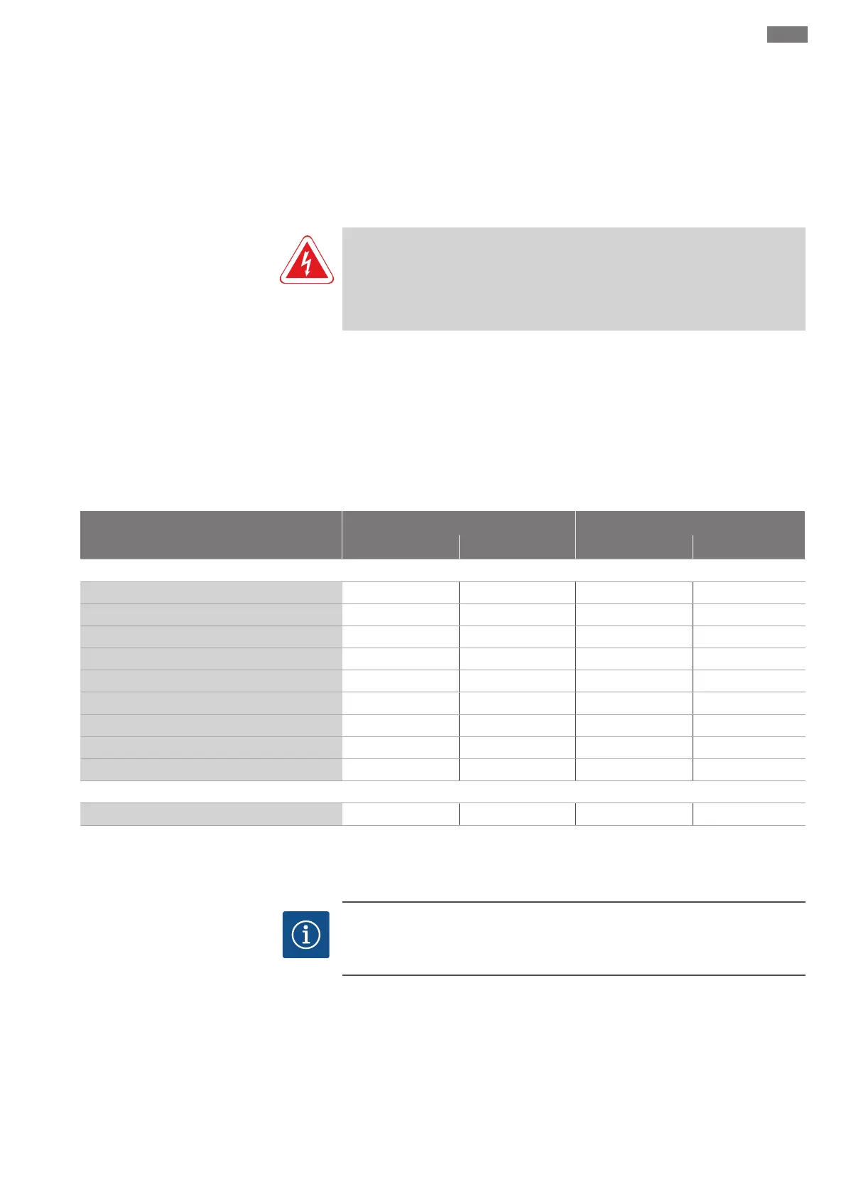
Overview of monitoring devices
Asynchronous motor Permanent magnet motor
T20.2 T20.2 T17.3...-P T20.2...-P
Internal monitoring devices
Digital Data Interface
− • • •
Motor winding: Bimetallic strip
• − − −
Motor winding: PTC
o • (+ 1...3x Pt100) • (+ 1...3x Pt100) • (+ 1...3x Pt100)
Motor bearings: Pt100
o o o o
Sealing chamber: conductive sensor
− − − −
Sealing chamber: capacitive sensor
− • • •
Leakage chamber: Float switch
• − − −
Leakage chamber: capacitive sensor
− • − •
Vibration sensor
− • • •
External monitoring devices
Sealing chamber: conductive sensor
o − − −
• = Standard, − = Not available, o = Optional
All the monitoring devices fitted must always be connected!
13.4.1 Motor with Digital Data Interface
NOTICE
Note the instructions for the Digital Data Interface!
Read the separate instructions for the Digital Data Interface and comply with them.
The Digital Data Interface evaluates all available sensors. Use the graphical user inter-
face of the Digital Data Interface to display current values and set the limit parameters.
A warning message or alarm signal is output upon exceeding the limit parameters. The
motor winding additionally features PTC sensors to enable secure pump deactivation.
The connection of the Digital Data Interface depends on the selected system mode and
other system components. Note installation suggestions and connection variants in the
instructions for the Digital Data Interface.
 Loading...