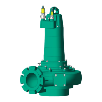
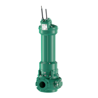
Product description en
Installation and operating instructions Wilo Motor T 17.3, 20.2:, EMU FA, Rexa SUPRA, Rexa SOLID 59
ƒ Controlling the pump with a frequency converter.
ƒ Controlling the complete system with up to four pumps.
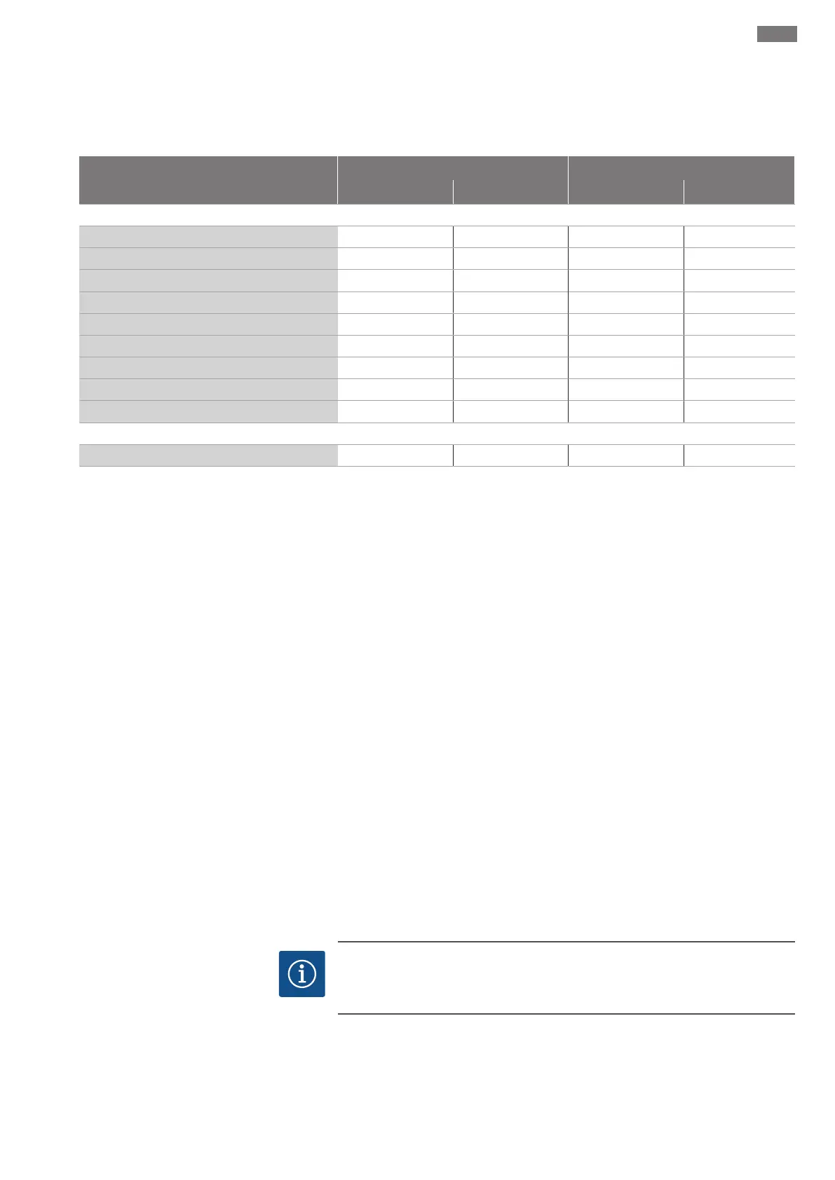
4.3 Monitoring devices
Overview of monitoring devices
Asynchronous motor Permanent magnet motor
T20.2 T20.2 T17.3...-P T20.2...-P
Internal monitoring devices
Digital Data Interface
− • • •
Motor winding: Bimetallic strip
• − − −
Motor winding: PTC
o • (+ 1...3x Pt100) • (+ 1...3x Pt100) • (+ 1...3x Pt100)
Motor bearings: Pt100
o o o o
Sealing chamber: conductive sensor
− − − −
Sealing chamber: capacitive sensor
− • • •
Leakage chamber: Float switch
• − − −
Leakage chamber: capacitive sensor
− • − •
Vibration sensor
− • • •
External monitoring devices
Sealing chamber: conductive sensor
o − − −
• = Standard, − = Not available, o = Optional
All the monitoring devices fitted must always be connected!
4.3.1 Motor without Digital Data Inter-
face
Motor winding monitoring
Thermal motor monitoring protects the motor winding from overheating. A temper-
ature limiter with a bimetallic strip is fitted as standard. Once the activation temper-
ature has been reached, deactivation with reactivation lock must take place.
Optionally, the temperature can also be measured using a PTC sensor. Thermal motor
monitoring can also be designed as temperature control. This allows two temperatures
to be measured. Once the low activation temperature has been reached, an automatic
reactivation can be initiated after the motor has cooled down. The unit is forced to de-
activate with reactivation lock once the high activation temperature has been reached.
External monitoring of the sealing chamber
The sealing chamber can be equipped with an external pencil electrode. The electrode
registers fluid ingress through the mechanical seal on the fluid side. An alarm or deac-
tivation of the pump can therefore take place by pump control.
Leakage chamber monitoring
The leakage chamber is equipped with a float switch. The float switch registers fluid in-
gress through the mechanical seal on the motor side. An alarm or deactivation of the
pump can therefore take place by pump control.
Monitoring of motor bearing
The thermal monitoring of the motor bearing protects the roller bearings against over-
heating. Pt100 sensors are used for temperature measurement.
4.3.2 Motor with Digital Data Interface
NOTICE
Note the instructions for the Digital Data Interface!
Read the separate instructions for the Digital Data Interface and comply with them.
The Digital Data Interface evaluates all available sensors. Use the graphical user inter-
face of the Digital Data Interface to display current values and set the limit parameters.
A warning message or alarm signal is output upon exceeding the limit parameters. The
motor winding additionally features PTC sensors to enable secure pump deactivation.
 Loading...