10
OPM-109
REV A
STARTING PROCEDURE
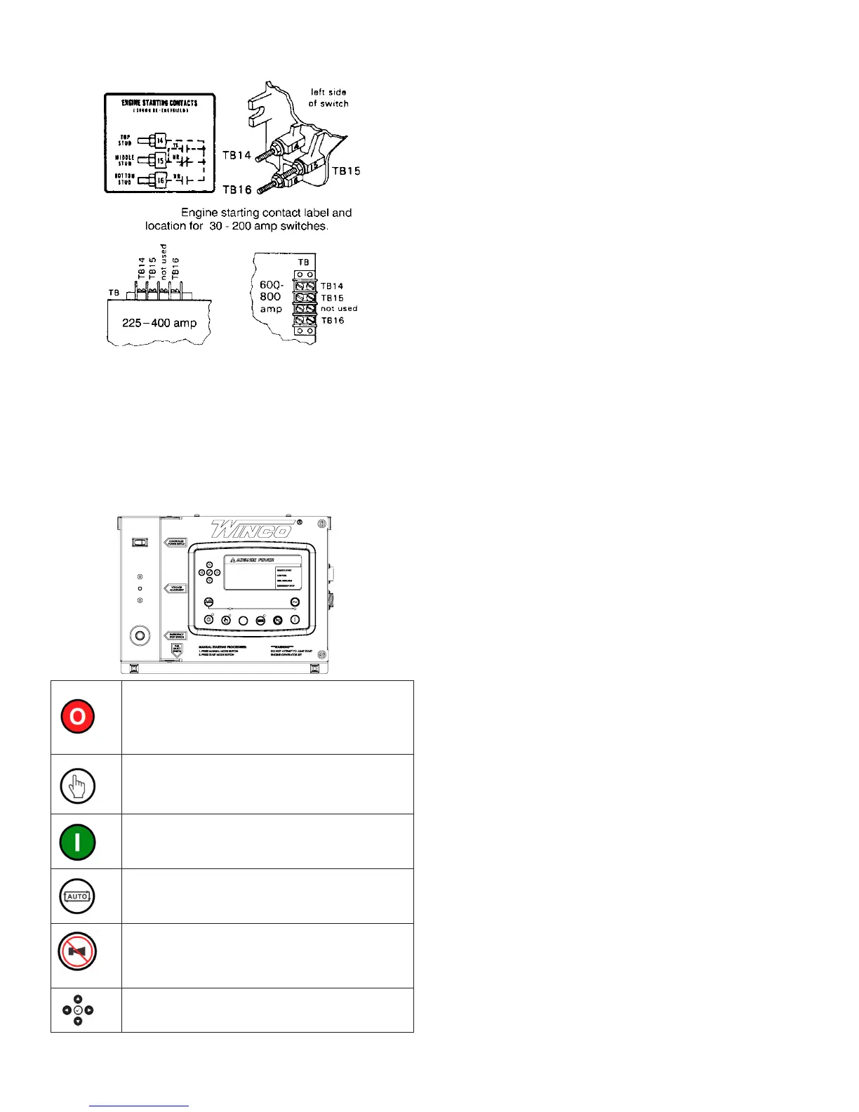
CONTROL LAYOUT
STOP/RESET-ThisbuttonplacesthemoduleintoitsStop/Reset
mode. This will clear any alarm conditions for which the triggering
criteriahavebeenremoved.Thefuelsupplyde-energizesandthe
engine comes to a standstill. Should a remote start signal be present
while operating in this mode, a remote start WILL NOT occur.
MANUAL MODE - This button places the module into its Manual
Mode. Once in Manual Mode, the model responds to the Start button
to start the generator and run it off load.
START-PressingthisbuttonfromSTOP/RESETwillstarttheengine
and run the load.
AUTO MODE - This button places the module into its Auto Mode.
This mode allows the module to control the function of the generator
automatically.
ALARM/LAMPTEST-Thisbuttonsilencestheaudiblealarmin
thecontroller,de-activatestheAudibleAlarmoutput(ifcongured)
and illuminates all of the LEDs on the module’s face as a lamp test
function.
MENU NAVIGATION - Used for navigating the instrumentation, event
log,andcongurationscreens.
PROTECTIONS
Whenanalarmispresent,thecommonalarmLEDifcongureswill
illuminate. The LCD display will show an icon to indicate the failure.
WARNINGS
Warnings are non-critical alarm conditions and do not affect the
operation of the generator system, they serve to draw the operator’s
attention to an undesirable condition. Warning alarms are self-resetting
when the fault condition is removed. The icon will appear steady in the
display.
SHUTDOWN
Shutdowns are critical alarm conditions that stop the engine and draw
the operator’s attention to an undesirable condition. Shutdown alarms
arelatching.ThefaultmustberemovedandtheSTOP/RESETbutton
pressedtoresetthemodule.Theiconwillbeashinginthedisplay.
INITIAL START UP
WARNING: EQUIPMENT DAMAGE:
Before attempting to start this unit, complete your pre-start checklist
and ensure the generator mainline circuit breaker is in the proper
position prior to starting. Starting this unit without it properly connected
can cause serious personal injury or equipment damage.
DO NOT jump start these engine-generator sets. Starting these units
on a low battery or jump starting them will cause damage to the engine
control module.
Use the following check list to verify correct installation before starting
the engine.
□Engineoil.Fillasrequiredwithpropergrade/qty.
□ Engine coolant. Fill as required with proper mixture.
□ Unit mounting base properly bolted down.
□ Clearance for service and maintenance on all sides.
□Properfuellinematerialandsize.
□ All fuel line connections tight.
□ Battery connections clean and tight
□ Battery fully charged.
□ All AC and DC wiring installed and properly protected.
□Compressoroil.Fillasrequiredwithpropergrade/qty.
After completing the previous checklist, the engine-generator set is
ready for initial start-up.
MANUAL MODE
1. Press and release the MANUAL MODE button. The small LED light
next to it should come on.
Note: There is no start delay in this mode of operation.
2. Press and release the green START ENGINE button. The DSE7310
will send two signals to the engine. The first signal wire #21 will engage
the fuel solenoid, the second wire, #22, will engage the starter on the
engine. At this point the DSE7310 will start the cranking cycle (10
secondsonand10secondsoff).
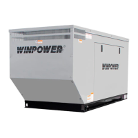
ASCO 300 UL SWITCH
Your DC connection points in the ASCO 300 ATS terminals “14” and
“15”.Dependingonthesizeoftheswitch,theyarelocatedindifferent
locations.
135060-00
60708-165
A - Customer Remote Start CONNECTIONS TERMINALS. The
two remote start leads from the Automatic Transfer Switch are
connected to the two terminals marked GROUND & START. The
wire in terminal GROUND is Battery Negative and the wire in the
terminal labeled START is your Remote Start lead. Closing these
two leads together will signal the DSE 7310 to go into an auto-
start mode and start up the engine generator.
Depending on the distance, 14 to 16 gauge stranded wire
should be used. It is suggested that these wires be labeled S1
JURXQGDQG6VWDUW The terminal blocks are designed to
use terminal lugs on all wires and the screws should be torqued
to 9.6 in. lbs.
1RWH$Q\UHOD\FORVXUHFDQEHXVHGWRVWDUWDQGVWRSWKLV
JHQHUDWRU$VORQJDVWKHFRQWDFWVWD\VFORVHGWKHHQJLQH
JHQHUDWRUVHWZLOOFRQWLQXHWRUXQ2QFHWKHUHOD\LVRSHQHG
WKHXQLWZLOOVKXWGRZQDQGUHPDLQLQWKHVWDQGE\PRGHXQWLO
WKHUHPRWHVWDUWUHOD\LVFORVHGDJDLQ
B - ESTOP- & ESTOP+. Remote Emergency Stop terminals.
These two terminals are shipped with a jumper installed. If your
application requires the installation of a Remote Emergency
Stop switch, remove the jumper and wire your switch to these
terminals. This unit will not start and run without either the
jumper installed or a remote N/C switch installed..
C. - Battery Charger Failure. Battery charger failure relay input
from remote battery charger to DSE7310 controller.
D - Remote Display Panel Interface Terminals. These
interface terminals are prewired to allow for the connection of a
remote display. This display allows for the remote annunciation
of alarms at a location such as a nurses station or a control
room. This display can used to meet the remote annunciation
requirements of NFPA 110 standards. (This feature meets the
annunciation requirements in applications requiring NFPA110
level one protection.)
DC Interconnections to the
Automatic Transfer Switch
*************
***** WARNING *****
*************
%HVXUH(QJLQH*HQHUDWRULVLQWKH³2))´SRVLWLRQEHIRUH
you make any DC interconnections.
*******CAUTION******
1HYHUUXQWKH$&DQG'&ZLULQJLQWKHVDPHFRQGXLW
ASCO 185 UL SWITCH
<RXU'&FRQQHFWLRQSRLQWVLQWKH$6&2$76DUH
WHUPLQDOV³´DQG³RQWKHLQWHUIDFHWHUPLQDOEORFN
ASCO 300 UL SWITCH
Your DC connection points in the ASCO 300 ATS are terminals
³´DQG³´'HSHQGLQJRQWKHVL]HRIWKHVZLWFKWKH\DUH
located in different locations.
TB7
removable
terminal block
TB7–4, TB7–5, TB7–6
123456789
Figure 4. TB7 generator starting contact terminals.
Table A. Generat or St art Connections
When the Utility fails Terminals on Controller
contact closes TB7–4 and TB7–5
contact opens TB7–5 and TB7–6
 Loading...