12
OPM-109
REV A
TROUBLESHOOTING TABLE
Problem Possible Causes
Unit will not crank when power fails Digital genset not in AUTO
Transfer control switch not in
AUTOMATIC position
Incorrect wiring between ATS and genset
Defective control relay in ATS
Fuse(s)blownintheDSE7310
Defective DSE7310
Loose or dirty battery terminals
Defective starter
Defective start solenoid
Low/deadbattery
Engine won’t crank Low/deadbattery
Blown DC fuses
Defective DSE7310
Defective key switch
Loose or dirty battery terminals
Defective starter
Defective start solenoid
Locked up engine genset
Defective engine harness
Improper battery voltage to start solenoid,
fuel pump, or fuel solenoid
Engine cranks but will not start Improper fuel delivery to the unit
Fuel supply shut off
Fuel tank empty
Air in the fuel system
Engine fuel solenoid has not opened
Defective fuel pump
Defective fuel solenoid
Defective engine harness
Improper battery voltage to fuel pump or
fuel solenoid
Engine starts, then stops and alarm
light comes on
Engine oil pressure is low
Engine has high water temperature
Engine has overspeed
Engine has gone into overcrank
No output from AC generator
Loss of speed signal
Loss of run signal
Engine will not come up to speed
after it starts
Insufcientfuelvolumegettingtotheunit
1. Too small of fuel line
2. Fuel racks not open properly
Governor is defective
AC short in generator components
ATS will not transfer to Emergency
Supply(generator)
No AC generator output
Defective ATS control board. See ATS
manual
Circuit breaker open or defective
ATS will not re-transfer to normal
power
Proper power line not available at line
terminals in ATS panel
Defective ATS control board. See ATS
manual
No AC output from generator Defective diode
Defective voltage regulator
Defective rotor
Defective stator
Defective exciter rotor
Defective exciter stator
AC short in the output leads
Defective/opengeneratoroutputbreaker
Wiring error
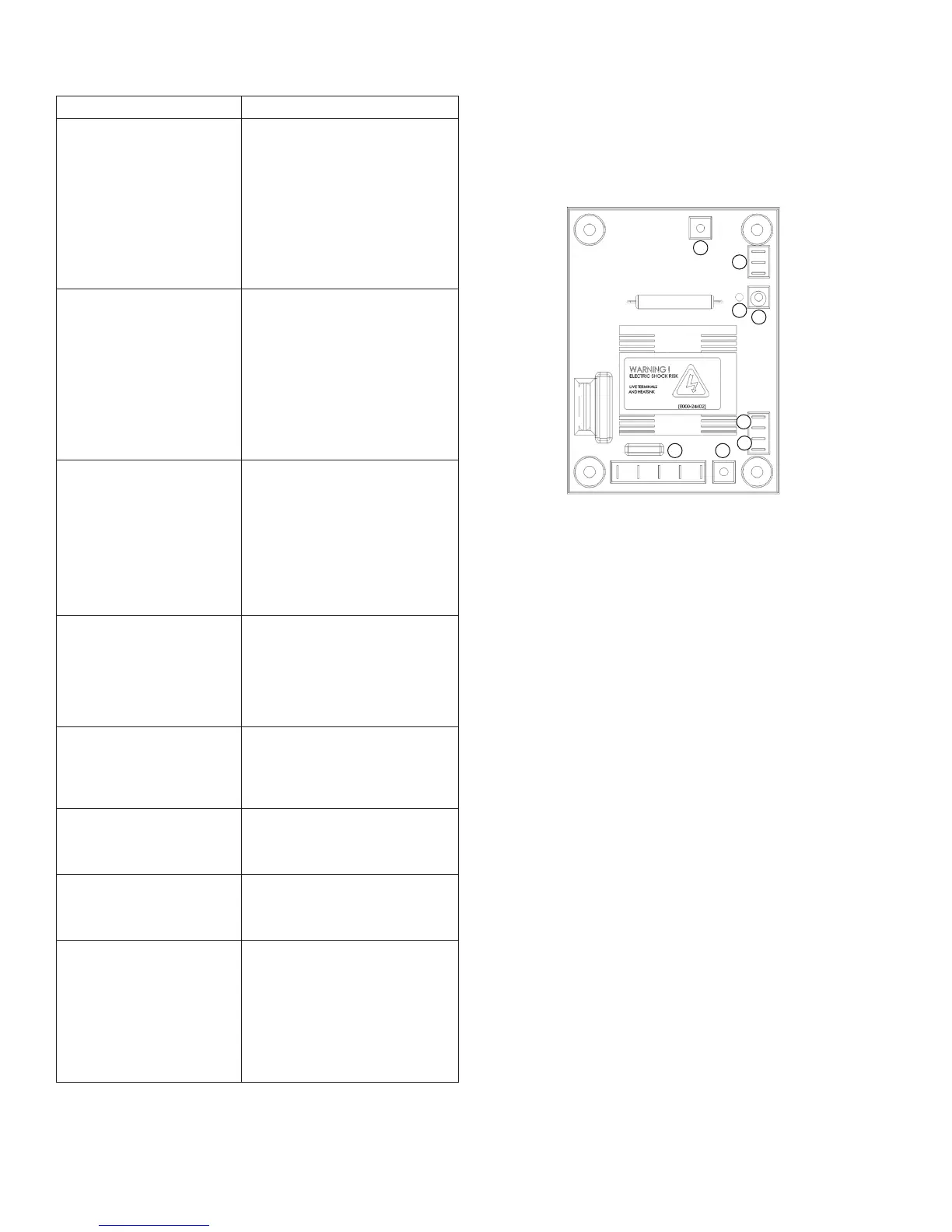
VOLTAGE REGULATOR WIRING
AS480AutomaticVoltageRegulator
The following is a list of connections on the AVR. These have been
factory set and other than voltage adjustment, should never be
changed.
1.GeneratorACsensingconnection(6,7,&8)
FieldvoltageDC(F1&F2)
2. Voltage adjustment
3. External voltage treatment rheostat.
No external rheostat - link 1 & 2
With external rheostat - 1 & 2 unlinked, connect external rheostat
leads to 1 & 2
4. AVR input selection
Highvoltage208/240/277-nolinkbetween3&4
Low voltage 120 - link 3 & 4
5. Under Frequency Roll Off adjustment
6. Under Frequency Roll Off indication light
7. Frequency selection:
50Hzoperation-linkCto50
60Hzoperation-linkCto60
8.Stabilitycontrol
8
1
2
3
4
50
60
C
7 6 F1 F2
1
3
4
6
7
8
5
2
AR480