8
OPM-109
REV A
WARNING:
Make sure the generator is disconnected from the battery to prevent
accidental starting.
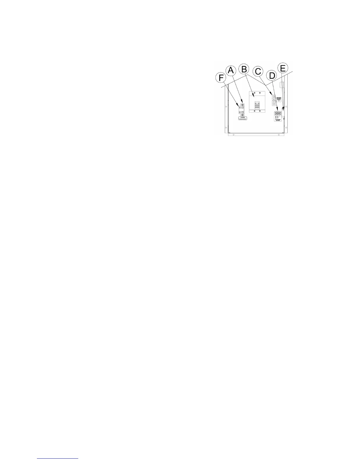
The connection box shown are typical arrangements.
A. NEUTRAL LUGS:
These lugs are isolated from ground and provided for you to connect
your neutral wire from the transfer switch to the generator.
The225Ampterminalblocklugswillhandlewiresize#4to300MCM
and should be torqued to 250 in. lbs.
B. GENERATOR CIRCUIT BREAKER:
This circuit breaker provides overload protection for the generator. Your
power feeds from the transfer switch will connect the bottom lugs on
the circuit breaker. The generator power feeds have already been wired
into the upper lugs.
Please refer to the circuit breaker installed on your unit for breaker lug
capacitiesandpropertoquespecications.
Toselecttheproperconductorsizebetweenthegeneratorandthe
ATS,rstlookyourmodelupinTable1ofAppendix“A”foryour
generator amperage, found further in this manual. Then refer to
Appendix“2”forguidanceonwiresizingbasedonbothwiretypeand
amperage.
Foradditionalinformationonwiresizes,refertotable310-16ofthe
NationalElectricalCodeANSI/NFPA70.
C. GROUND LUG:
These ground lugs are bonded to ground and are provided for you
to connect your ground wire from the transfer switch to. The lugs will
accommodate#10AWGto2/0AWGandshouldbetorquedto200in.
lbs.
D: 120V GFCI CIRCUIT TERMINAL BLOCK:
Theseterminalsareratedfor85Ampsandwillhandlewiresizes#4
AWGto18AWG.Theyshouldbetorquedto16in.lbs.Thiscircuitmust
be fed from a fused circuit in the distribution panel and provides power
for the blockheater and the battery charger.
E:120V/20AMPDUPLEXRECEPTACLE:
This convenience receptacle is used to power both battery charge and
blockheater. This circuit must be fed from a GFCI fused circuit in the
distribution panel.
A.C. ELECTRICAL CONNECTIONS
NOTICE: CLASS 1 WIRING METHODS ARE TO BE USED FOR ALL
FIELD WIRING CONNECTIONS TO TERMINALS OF A CLASS 2
CIRCUIT
All wiring must be completed in accordance with the National Electric
Code as well as any state and local codes.
Youmustpayparticularattentiontowiresizerequirementfor
the amperage of service you are dealing with. The table below
providesyouguidanceonwiresizingbasedonbothwiretypeand
amperage. Wire amperages have been derated for 40° C ambient
temperatures operation.
The block heater on this unit is a 750 watt heater can use the same
20 Amp GFCI fused circuit. This circuit will terminate on the 120
Volt terminal block mount in the customer connection cabinet. The
engine blockheater installed on this unit should also be plugged into
this receptacle. The block heater is thermostatically controlled when
plugged in will maintain the engine coolant temperature between 100
and 120 degrees F.
MOUNTING THE AUTOMATIC TRANSFER SWITCH
WARNING: FIRE HAZARD:
All wiring must be done by a licensed electrician, and must conform to
the National Electrical Code and comply with all the local codes and
regulations. Check with the local authorities before proceeding.
INSTALLATION NOTES:
Because of many different types of service, feeder and distribution
equipment,nospecicwiringinstructionscanbeprovided.Itis
recommended that only copper wire be used. In all cases it is
essential that while the load is connected to the generator, there can
be absolutely no feedback from the generator to the power line or the
power line to the generator. When properly installed, the normal ATS
Control and safety system will eliminate all paths and feedback.
Towiretheautomatictransferswitchintoexistingwiring,rstdetermine
which circuits will be on the emergency load circuit. If the entire load is
transferred, the transfer switch can be wired directly after the watt-hour
meter and the service entrance, providing the service entrance ampere
rating is within the transfer switch’s rated capability.
Ifonlyspeciccircuitsaretobepoweredunderemergencypower
failure conditions, an additional distribution panel designated
“emergency distribution panel” must be installed.
All selected emergency circuits are removed from main distribution
panels and installed in the emergency distribution panel. The ATS is
then installed between the main panel and the emergency distribution
panel.Suggestedcircuits:freezer,refrigerator,furnace,emergency
lights, sump pump, emergency outlet circuits, etc. Total running load
must not exceed generator rating.