4
OPM-109
REV A
SPECIFICATIONS
DR20I4
Generator
Wattage 20,000 20,000 20,000 20,000
Volts 120/240 120/208 120/240 277/480
Phase Single Three Three Three
PF 1.0 .80 .80 .80
Amps 83 69 60 30
CBSize 90 75 60 30
Hertz 60 60 60 60
Engine
Model Isuzu4LE12.2L
Starting System 12 Volt
Mufer Standard
FuelConsumption(fullload) 1.8Gal/Hr
Generator Testing Resistance
Model Stamford PI144D1J
Winding Group 311
Resistances:
Rotor 0.657 Ohms @22°C
Stator 0.377 Ohms Per Ph @ 22°C
ExciterRotor 0.228OhmsPerPh@22°C
ExciterStator 18.5Ohms@22°C
VoltageRegulator AS480
EngineFluidSpecications
Fuel ASTM D-975 -1D or 2D
EN590 or equivalent
Oil Type SEE LUBRICATION SECTION
OilCapacity 8.8Quarts
CoolingSystem 50/50mix
INTRODUCTION
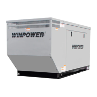
PRODUCT DESCRIPTION
This engine-generator set is designed for unattended remote start
operation. It can be operated as part of a fully automatic standby power
system or independently as a local start unit in a prime power system.
The engine-generator set is fully tested at the factory prior to shipment
to insure proper operation of each individual component as well as the
total system’s performance and reliability.
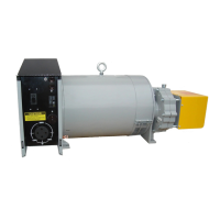
The engine generator set consists of a multi-cylinder, liquid cooled
enginenominallyoperatingat1800rpm.Thegeneratorfrequency
regulationismaintainedbytheenginegovernortowithin+/-1.5Hz
(cps),fromnoloadtoratedloadforstandardmechanicalgovernors
andtowithin+/-.5Hzorbetterforunitsequippedwithanelectronic
governor.Thegeneratorisasinglebearing,directdrive,rotatingeld
design.Thegeneratorisconnectedtotheengineywheelviaexible
drive disks. Generator set is skid mounted with isolation mounts
between the engine and base on all units.
A customer supplied 12 Volt battery is required to complete the
installation. Battery requirements are listed later under the battery
installation section.
Unit Orientation Note: All references used in this manual for unit
familiarization,accessandcomponentlocationsontheGeneratorSet
areorientedfromaTOP(plan)VIEWwithengineattheFRONTand
generator to the REAR.
WINPOWER uses a common junction box for all customer control and
powerconnections(bothACoutputandDCcontrol).Thecommon
electrical junction box is always on the left side at the generator end of
the machine.
The engine is controlled and Generator Set operation is monitored for
safe operation by a programmable microprocessor based electronic
EngineControlModule(ECM)withanLCDdigitaldisplay.The
generator set ECM control is mounted on a vertical pedestal on the
right side of the generator. The ECM is programmed with a cycle
crankingsequence-3cyclesof15secondson/15secondsoff,and
5 minute cool-down delay. The cool-down delay can be changed in
theeldfrom0to30minutesbyyourinstaller.Otherfeatures,timing
cycles, set points, and signal output capabilities are possible. Consult
factory for procedure and passwords.
NOTICE:
These units will automatically transfer if a power outage occurs while
running in exercise mode.
GENERATOR SET
Every WINCO generator set has its own unique identity data plate.
Thisdataplateidentiesthecompleteunitmodelnumber,thesystem
serial number, and has links to the individual components that form the
generator set in our factory records. Several of the major components
also have their own individual data plates providing additional
information to document build data for warranty and replacement parts.
ENGINE
Refer to the engine operators manual for more detailed operation and
maintenance information.
CAUTION: EQUIPMENT DAMAGE:
Be sure to check the engine oil level frequently as specied in the
engine manual.
The engine manufacturer has established an excellent worldwide
engineserviceorganization;engineserviceisavailablefromanearby
authorizeddealerordistributor.GototheWINCOwebsiteforalistof
enginedealers(http://wincogen.com/Engine_Support)orcontactthe
WINCO Service Department.
The rated power of each engine-generator is limited by the
temperature,altitude,andallotherambientconditionsspeciedby
the engine manufacturer. Engine power may decrease 3½% for each
1000 feet above sea level, and will decrease an additional 1% for each