BEETLE /M-III User Manual 19
System Unit
Always make sure that the system is switched off when you do cabling
works.
Connecting peripherals with the system switched on is not allowed.
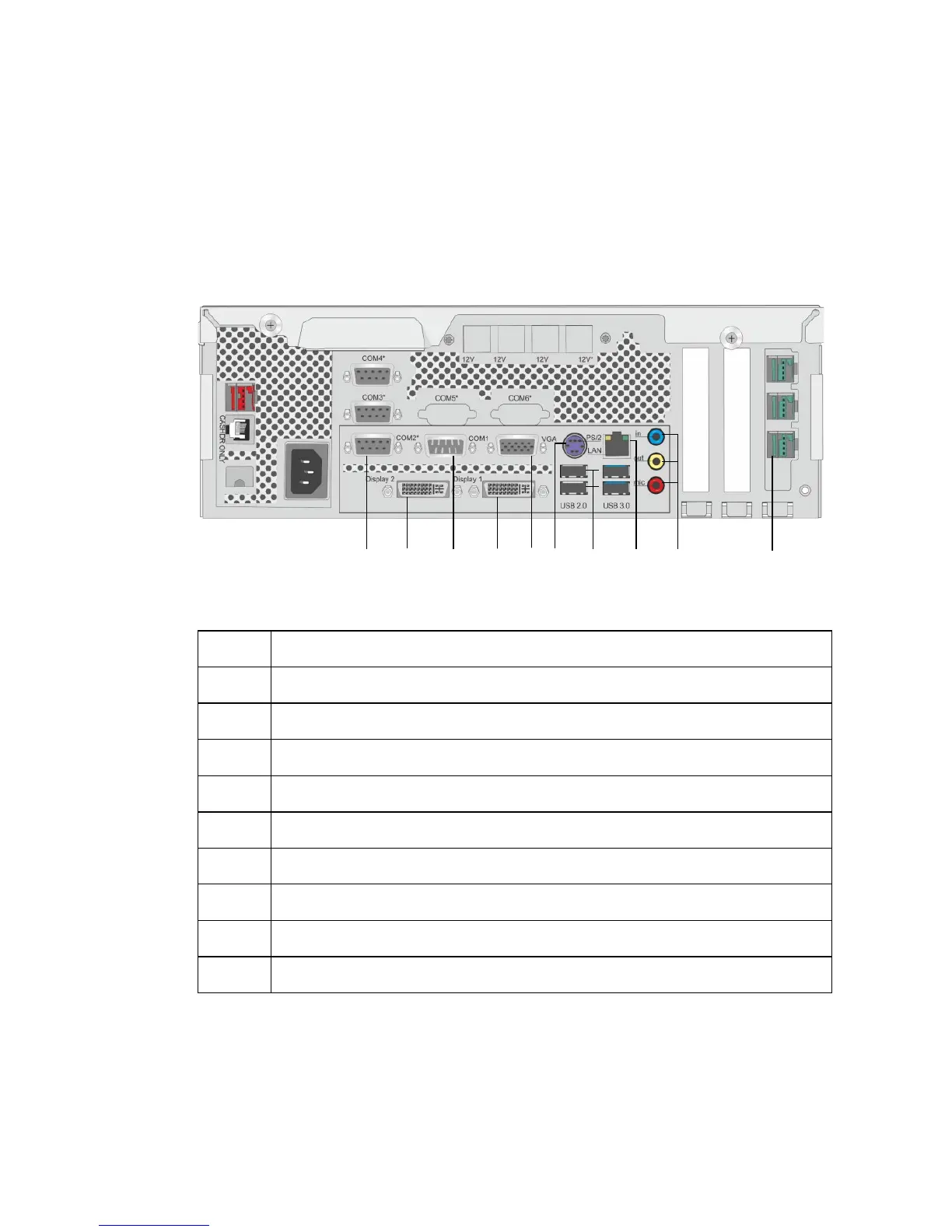
Example for a connector panel of the BEETLE /M-III:
3 x D- Sub (COM2*/COM3*/COM4*, power supplied)
Display 2 (DVI-D/PLINK2) w/o RMT
1 x D-Sub (COM1 interface)
Display 1 (DVI-D/PLINK2) with RMT
Mini DIN (KYBD), keyboard
2 x USB- A (USB 2.0)| 2 x USB- A (USB 3.0)
3 x jack plug, 3.5 mm (In, Out, microphone)
⑩
3 x PoweredUSB 12V
 Loading...