2
Boot Collar
ALL MODELS
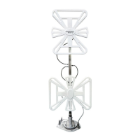
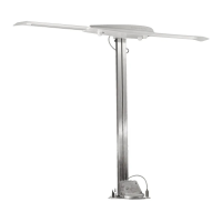
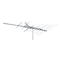
STEP 6: Attach antenna head to lift tubes with two
(2) steel pins, Figure 6. Align holes in leveling
bracket on back of antenna head with holes in lift
tubes, insert pins and secure in place with (2) E-clips.
Use pliers and get a firm grip on E-clips. Fit clips
into groove on pins and snap into place.
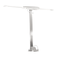
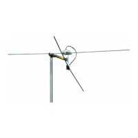
STEP 7: On models made before March, 2004,
attach coax connector to jack on back of antenna
head, slide weather boot into place over boot collar;
shown in Figure 7A. On models made after March,
2004, attach weather resistant coax connector to jack
on back of antenna head; shown in Figure 7B.
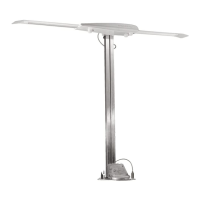
STEP 8: Mount antenna and lift on roof in travel
position. Apply a liberal amount of approved
nonhardening sealing compound on bottom of base
plate and roof area around hole, Figure 8. Secure
base plate with screws provided. Apply sealing
compound over mounting screws, Figure 8.
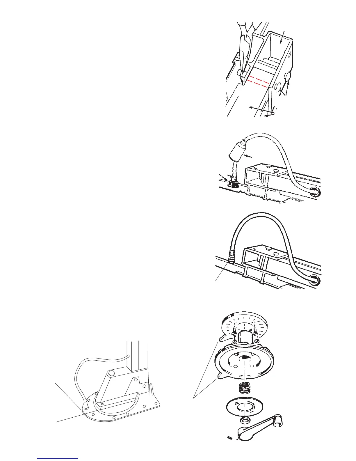
STEP 9: Lay ceiling plate on top of directional
handle with pointers aligned and slide assembly over
rotating base shaft in ceiling. Make pilot holes in
ceiling. Mount ceiling plate with directional
handle in place with screws provided, Figure 9.
STEP 10: Assemble directional handle, spring, nylon
bearing, directional handle decal and elevating crank
as shown in exploded view in Figure 9. Remove
backing from crank cover decal and press firmly
inside directional handle. Slide all parts over
elevating shaft and install elevating crank so set
screw is on one of the six flat sides of elevating shaft
before tightening screw.
WARNING: Once set screw touches shaft, tighten
only 1/4 turn more. Set screw simply holds
elevating crank on. DO NOT OVERTIGHTEN!
NON-AMPLIFIED MODELS ONLY
STEP 11: Run downlead to TV set location and make
connection to antenna terminals of TV set.
Leveling Bracket
(2) Steel Pins
Lift Tubes
(2) E-Clips
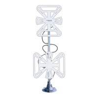
Antenna
Head
Coax Connection
FIGURE 7B
FIGURE 6
NOTE:
Apply non-
hardening sealing
compound such as
Butyl caulking
between Base
Plate and roof
of vehicle
CAUTION:
Do not get sealing compound on bearing surface between
base plate and Rotating Gear Housing. Do not paint top of
Base Plate or around Rotating Gear Housing.
FIGURE 8
FIGURE 7A
CEILING PLATE
DIRECTIONAL
HANDLE
SPRING
DECAL
NYLON BEARING
ELEVATING CRANK
Coax Connection
Weather
Boot
FIGURE 9
POINT TO REAR
OF COACH