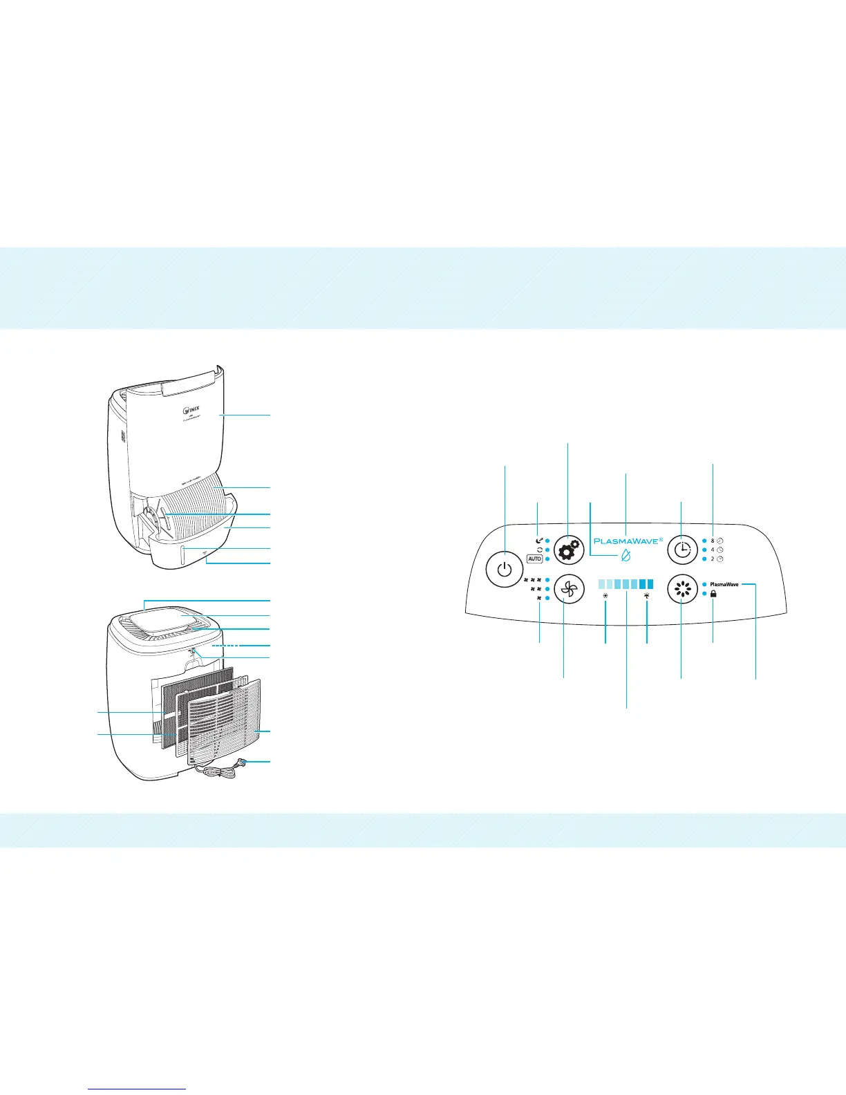
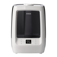
PRODUCT DIAGRAM CONTROL PANEL
1211
Power
Function Button
1. Continuous Mode : Unit operates continuously based on the fan speed
selected by user regardless of ambient humidity. (Low/Medium/High)
2. Sleep Mode : Dims control panel lights and sets the unit to operate at
lowest fan speed.
3. Auto-Mode : Unit runs until ideal humidity level is reached and shuts off
intermittently to save energy (Green “Comfort Zone”).
Mode
Indicator
Low Water
Indicator
Timer Indicator
PlasmaWave
(ON/OFF Indicator)
Timer Setting
Button
Fan Speed
Indicator
Fan Speed Button
(Low, Medium, High)
Low
Humidity
Indicator
High
Humidity
Indicator
PlasmaWave
(ON/OFF) Button
Control Panel
Lock Indicator
Humidity Level Indicator
Displays humidity level, when desirable level of humidity
levels are reached they will be displayed in the green “Comfort Zone”
Orange : Low Humidity (Below 30% RH)
Blue : High Humidity (61-70% RH)
Green : Ideal Humidity (40-60% RH)
PlasmaWave
(ON/OFF)Indicator
Control Panel Display
Water Level Indicator
Antibacterial Water Tank
(CleanCel
)
Antibacterial Disk Handle
Antibacterial Disk (CleanCel
)
Rear Air Intake Grille Cover
Fan (Inside)
Combination Filter
Pre-Filter
Front Panel
Power Plug
Water Tank Release Lever
Air Outlet
Air Outlet Cover
Air Outlet Release Button