SSD201/202 7-inch Smart Display User manual
10
/14
Wireless-Tag Technology Co., Limited http://www.wireless-tag.com
Table 7. RTP interface definition
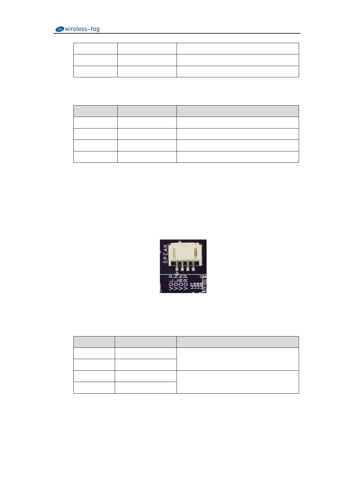
3.5 Speaker Interface
The motherboard leads out a dual-channel speaker interface through a 4Pin PH2.0 horizontal
connector. Each channel supports 8ohm/1W speaker. The pin definitions of the speaker interface
are shown in Table 8.
Figure 7. Speaker interface diagram
Table 8. Speaker interface definition
Right channel speaker driver output
Left channel speaker driver output
3.6 DMIC Interface
The motherboard leads out a digital microphone interface through a 10Pin horizontal PH2.0


 To Next Page