SSD201/202 7-inch Smart Display User manual
7
/14
Wireless-Tag Technology Co., Limited http://www.wireless-tag.com
UART/RS232 data communication, with Baud Rate up
to 115200bps
UART/RS485 data communication, with Baud Rate up
to 115200bps
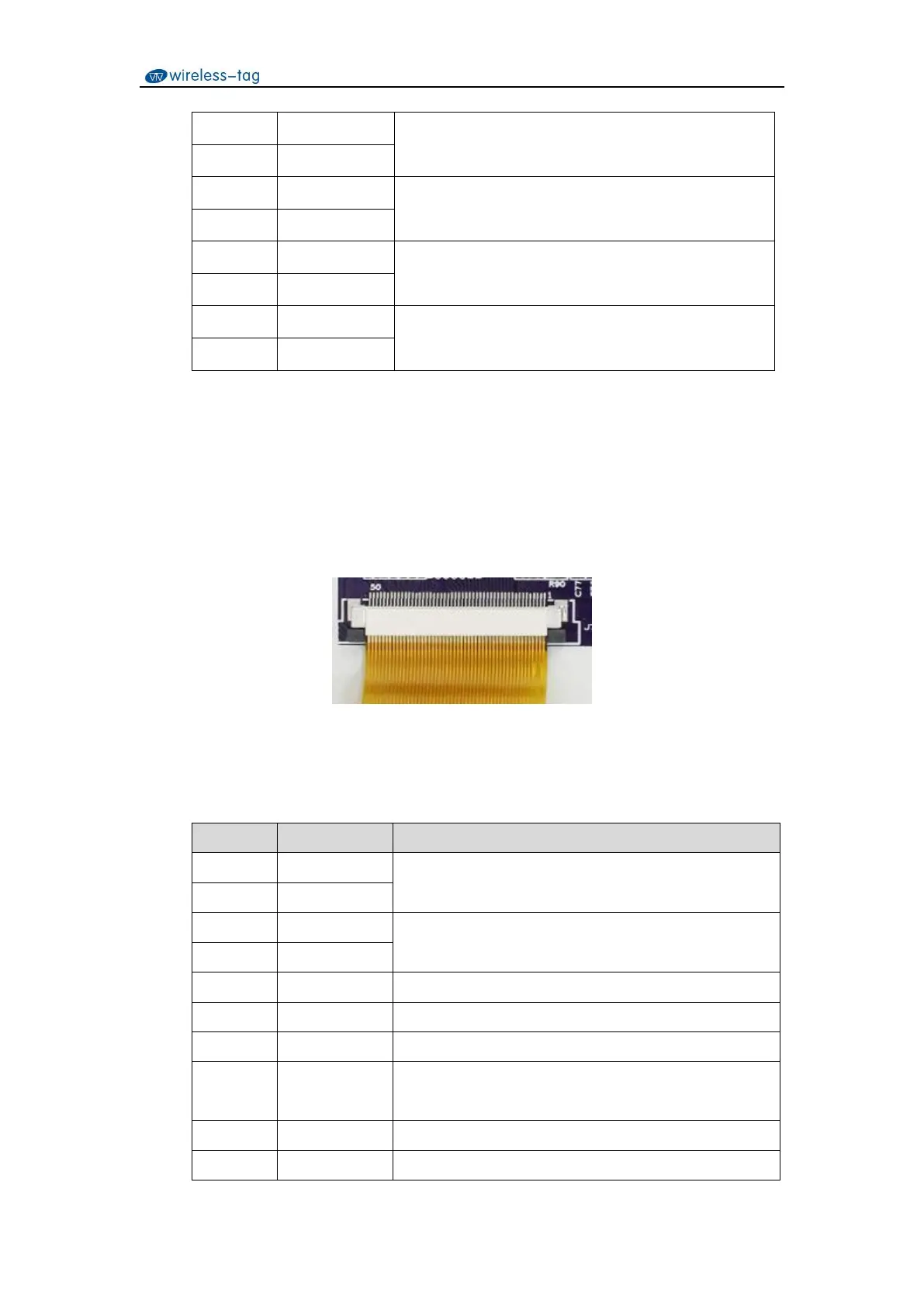
3.3 RGB Interface
RGB signal interface is led out by a 50Pin FPC0.5mm upper connector. The pin definitions are
shown in Table 5:
Figure 4. RGB signal interface pin diagram
Table 5. RGB signal interface pin definition
DE/SYNC mode select. Normally pull high
H: DE mode. L: HSD/VSD mode
Vertical sync input. Negative polarity