SSD201/202 7-inch Smart Display User manual
6
/14
Wireless-Tag Technology Co., Limited http://www.wireless-tag.com
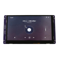
Figure 2. Front interface diagram of the motherboard
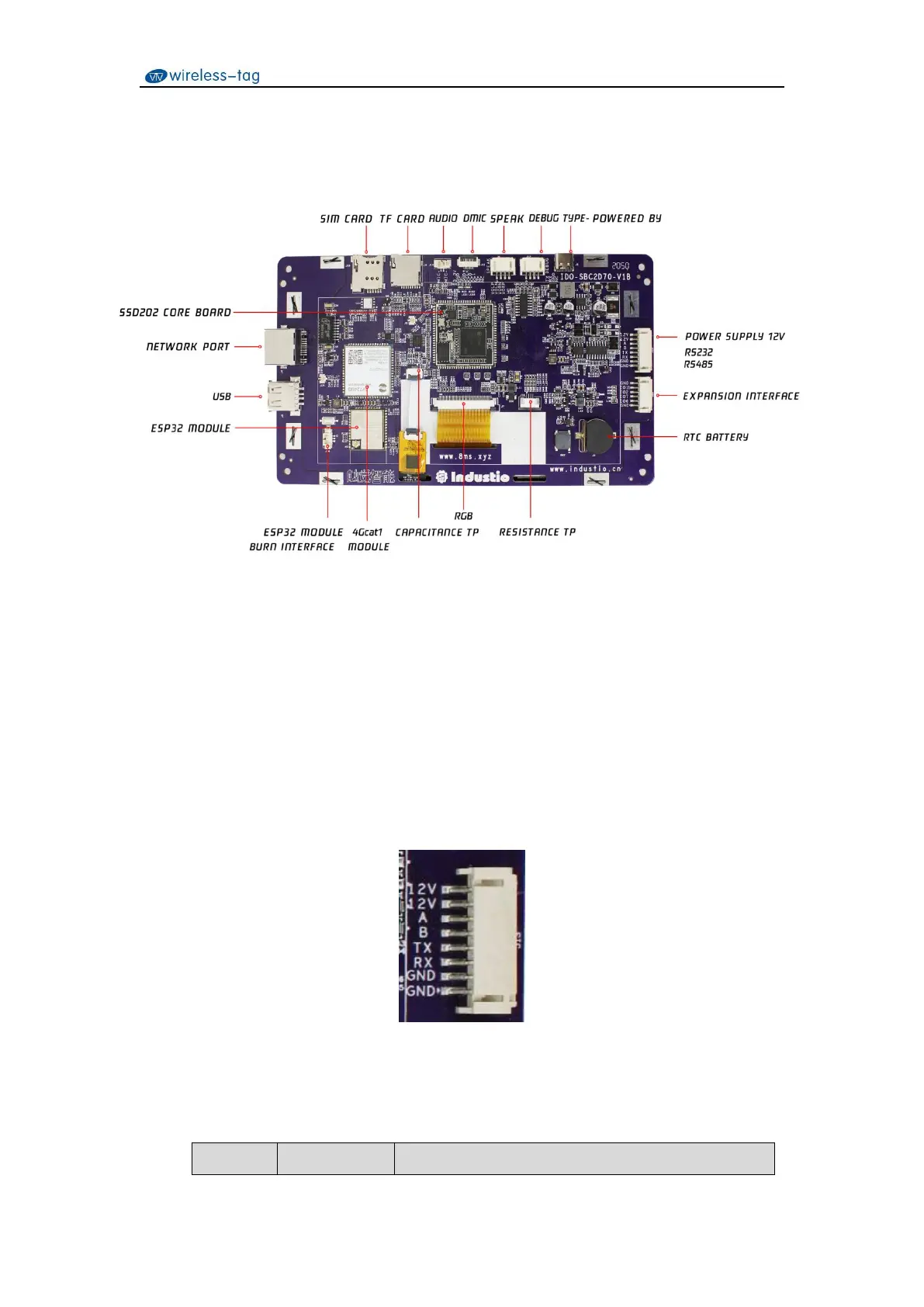
3.2 Power Interface/RS232/RS485
The default supply voltage is 12V@1A, 8Pin horizontal PH2.0 connector is adopted, and the
voltage range is DC 4.5V~30V. In addition, the motherboard supports 1-channel RS232 and
1-channel RS485, and the pin definitions are shown in Table 4:
Figure 3. Power interface/RS232/RS485 pin diagram
Table 4. Power supply/RS232/RS485 pin definition