Do you have a question about the Wixey WR700 and is the answer not in the manual?
File track edges for perfect alignment before joining track halves together with the wedge.
Position readout track when fence lock body is below the fence rail.
Position readout track when fence lock body is above the fence rail.
Carefully slide the readout onto the track assembly.
Use magnet bracket for Biesemeyer fences and clones on left side mount.
Use magnet bracket for Biesemeyer fences and clones on right side mount.
Use existing rail mounting bolts to attach mounting brackets for round rail fences.
Align track for shorter fences or specific measurement ranges.
Cut readout track to desired length using a hack saw if needed.
Position brackets on fence rail bottom, typically 1/2" from front.
Mark bottom of fence rail for drilling mounting bracket holes.
Center punch and drill holes, then drive thread forming screws with oil.
Use drill driver or ratchet wrench with upward pressure for thread forming screws.
Ensure sensor strip pattern is oriented 'UP' towards the sky.
Line up first strip, use gauge for second strip spacing, press firmly.
Touch a grounded surface before removing or installing batteries to prevent damage.
Adjust readout fit by tightening/loosening back screws; ensure easy slide but close contact.
Test the readout to confirm it functions properly after installation.
Bend and fabricate universal bracket for non-standard fence bodies.
Attach universal bracket to DEWALT fences using small drill and thread forming screws.
Bend bracket at a vertical line in a vice and cut off unused section.
Use universal mounting bracket options for Unifence and similar fences.
Use universal mounting bracket options for Vega and similar fences.
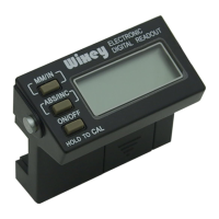
Push momentarily to turn ON/OFF; hold for 3-5 seconds to calibrate and set to 0.000.
Toggles between Absolute and Incremental measuring modes.
Toggles between Inch and Millimeter measurement modes.
Incremental mode re-sets to 0.000.
Toggle back to ABS mode; the dimension is remembered.
Check sensor strip orientation, readout looseness, or battery.
Install a new battery or clean battery contacts.
Remove and replace battery, wait 30 seconds.
Check readout looseness or static discharges from dust collectors.
| Brand | Wixey |
|---|---|
| Model | WR700 |
| Category | Power Tool Accessories |
| Language | English |