________________________________________________________________________________________
www.wnt.com XND.00004.023_A - 02/2018 22
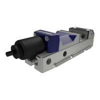
Position the stop pin
e.g. when replacing the mechanical force element.
Turn the mechanical force element into the spindle
nut.
Remove the guide component. (pos. 40)
Fit the stop pin (pos. 50) and lightly fix the threaded
pin (pos. 140) but do not lock.
Turn the spindle until the stop pin comes to a stop
at the spindle nut lug.
If this does not happen, turn the stop pin by 180°
and repeat the previous step.
Check that the pin has stopped.
Secure the stop pin with the threaded pin.
Fit the bearing washer, spacing washer and spring
washer. (HDG2 160: 3 instead of 2 spring washers)
Secure the countersink screw with screw lock,
medium tight.
Fit the guide component so that it protrudes on the
jaw side.
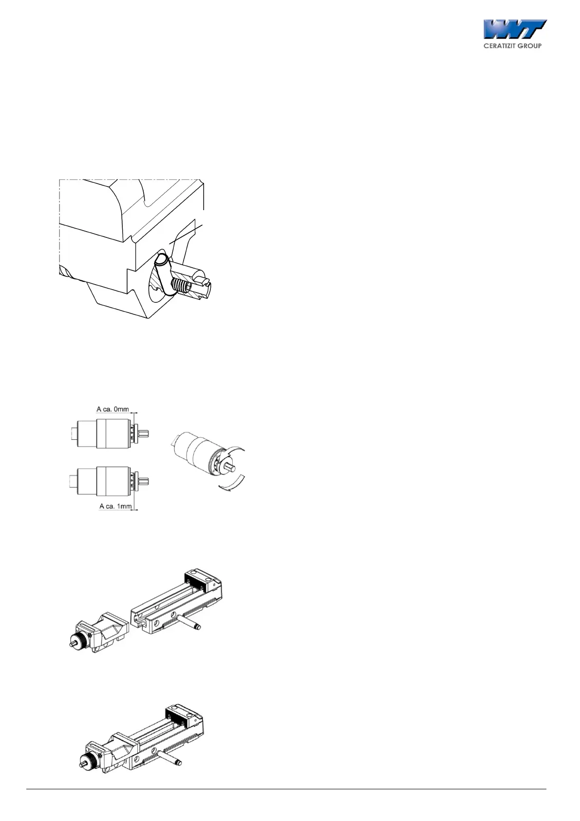
Setting ring does not move
Var. 1: Setting ring turned in too hard
Gap A is approx. 0 mm. To release the setting ring,
turn it anti-clockwise.
Var. 2: Setting ring turned out too much
Gap A is approx. 1 mm. To release the setting ring,
turn it clockwise.
7 Removing and replacing parts
7.1 Removal
Remove locking pin (pos. 60) and move out
carriage.
7.2 Installation
Insert the carriage and then the locking pin (pos. 60)
while adequately lubricating the guides, e.g. using
MOTOREX Supergliss 68 K lubricant to ISO VG 68.