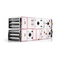
Power connection
Power connection
Thepowerconnectionmustonlybecarriedoutbytrained,qualiedelectricianstoa
standard compliant with the applicable regulations (VDE, local power utility, etc.).
If the intake air / exhaust air fan shuts down or fails, all control valves must
automaticallycloseandtheDHW/coldwaterandscrubberpumpsmustswitchoff.
Useonlycontrolvalvesthatclosewhende-energisedandantifreezethermostatswithout
disabled reset, as otherwise components will continue to operate even if the system
shuts down. Under such circumstances the built-in safety features will not be able to
function as intended (e.g. no assurance of effective frost protection).
Install a lockable repair switch for each drive motor to ensure that the air-handling unit
can be safely shut down.
If an additional protective equipotential bond is necessary due to structural requirements,
thismustbemanufacturedonsite.Itisthedutyoftheuserorthequaliedelectricianto
ensure that the appliance is properly earthed in accordance with the applicable national
and local electrical and installation regulations.
Once the power connection has been completed, the installation must be safety-tested
in accordance with VDE 0701 part 1 and VDE 0700 part 500 to check its full working
order and that the safety devices are fully operational.
Use only electric motors designed to drive fans.
Itisabsolutelyessentialtowirethemotorinaccordancewiththeconnection
schematicintheterminalbox.Amotorthatiswiredincorrectlywillbeunableto
developitsratedoutputandmaybedestroyed.
Use a PTC thermistor trigger for each motor with PTC thermistor, an interlock contactor
for each motor with thermo contacts and a thermal overcurrent relay for each motor
without PTC thermistor or thermistor contacts.
Use equipotential bonding and earth straps to ensure the protective conductor connection
between the air-handling unit and the ducts and between the heat exchangers and the
pipework installed on site.
ECmotorscanbeoperatedovertheentirespeedrangewithinniteadjustmentvia
a 0 - 10 signal (DC). The motors are generally equipped with internally switched
temperature controllers. Do not lay the control line of the device directly parallel to the
mains supply cable. Keep them as far apart as possible. Recommendation: Distance:
> 10 cm (separate cable routing)
If the EC fan is only connected to the power supply without connecting an additional
regulation or control device to the control connection of the fan, then a bridge must be
inserted between the connections 0 – 10 V /PVM and +10 V. In this case, the fan runs
at the maximum speed and/or air volume.
To restart the motor, switch the mains voltage off for at least 25 seconds, then switch
it on again.
Only universal current sensitive residual current circuit breakers (type B) are permitted.
We recommend residual current circuit breakers with a trigger threshold of 300 mA.
Voltage is present on terminals and connections even when the device is switched off.
Donottouchthedeviceuntilatleastveminuteshavepassedsincedisconnectingthe
voltage at all poles. If control voltage is applied or a setpoint speed is stored, the motor
restarts automatically, e.g. after a mains failure.
Note
Note
Motor malfunction
Residualcurrentcircuitbreaker
Electrical connection of
the EC fan
 Loading...