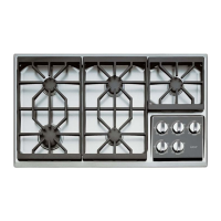
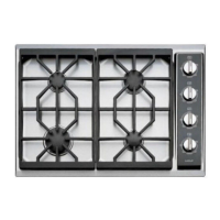
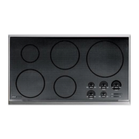
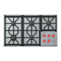
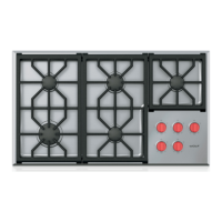
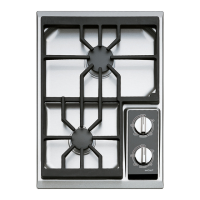
GGAASS CCOOOOKKTTOOPP--
GGAASS CCOOOOKKTTOOPP--
22
22
SSEERRIIEESS
SSEERRIIEESS
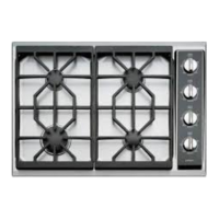
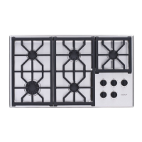
Installation Information
3-6
INSTALLATION PROCEDURE
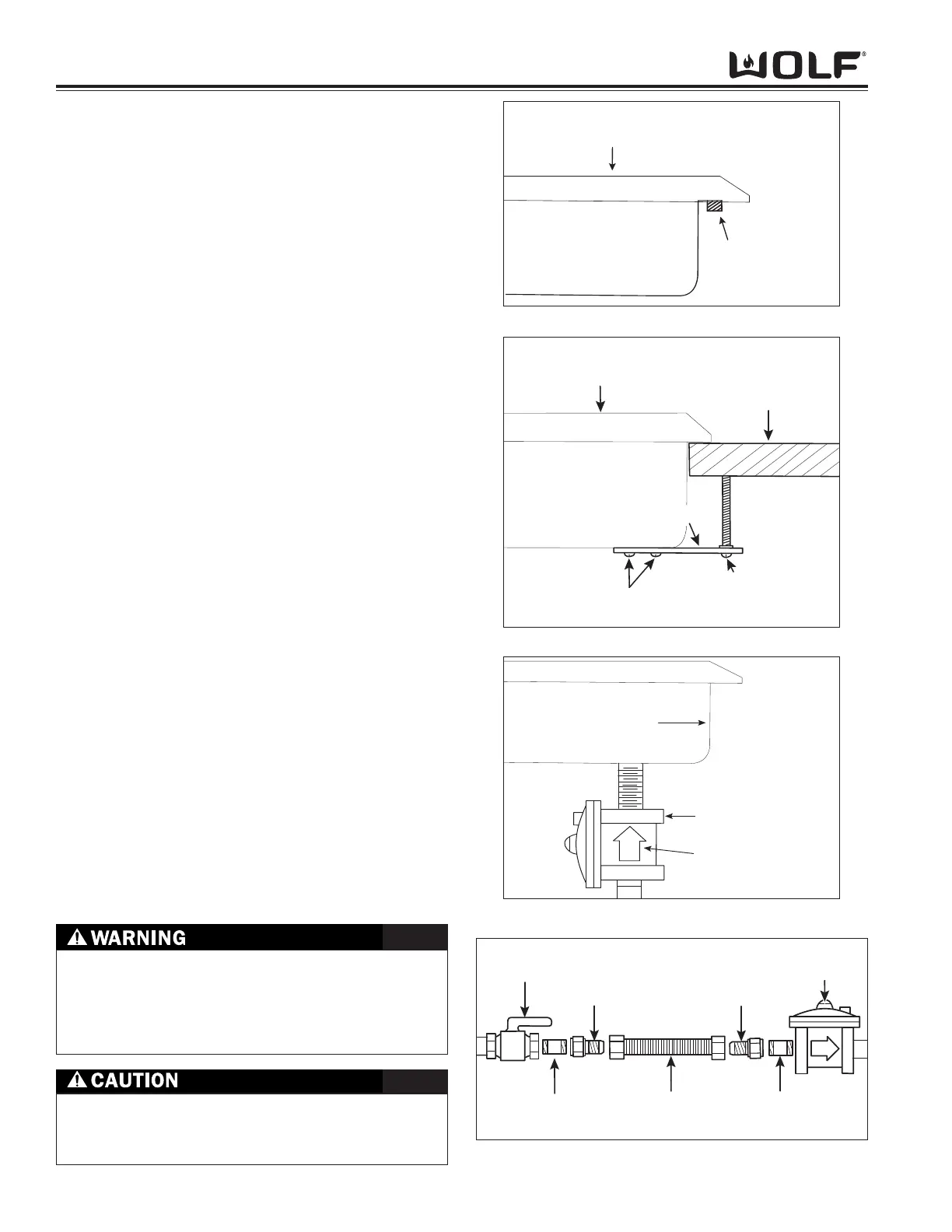
• Insert cooktop into countertop opening and
center cooktop. Check that front edge of
cooktop is parallel to front edge of countertop.
Check that all required clearances are met.
• Use a pencil to outline rear of cooktop on coun-
tertop. Then remove cooktop from countertop.
• Apply foam strip around bottom of burner box
flush with edge. (See Figure 3-8).
• Reinsert cooktop into countertop opening.
Check that cooktop is parallel to front edge of
countertop. Lift entire cooktop to make adjust-
ments, aligning with pencil line.
• Attach brackets to burner box. Insert clamping
screws into brackets. Use a screw driver to
tighten clamping screws against underside of
countertop. (See Figure 3-8).
Note: Do not overtighten screws.
• Install pressure regulator with arrow on regulator
pointing up towards unit and in a position where
you can reach the access cap. (See Figure 3-9).
• Assemble flexible metal connector from gas sup
ply pipe to pressure regulator. (See Figure 3-10).
• Use a pipe-joint compound made for natural and
LP gas. If a flexible connector is used, be certain
the tubing is not kinked.
Note: All connections must be wrench tightened.
Do not make connections to regulator too tight.
Making connections too tight could crack pres
sure regulator. Do not allow regulator to turn on
pipe when tightening fittings.
• Open shut-off valve in supply line. Wait a
few minutes for gas to move through line.
• Leak testing of appliance shall be conducted
accordingly using a soapy water solution or an
electronic leak detector.
The maximum gas supply pressure to the regulator
should never exceed 14” WC (Water Column
Pressure); 1/2 psi (3.5kPa)
NEVER USE OPEN FLAMES TO CHECK FOR GAS
LEAKS. ONLY USE A LEAK TESTING SOLUTION
OF SOAPY WATER OR AN ELECTRONIC LEAK
DETECTOR. DO NOT USE LIQUID NEAR VALVE
STEMS.