3
B E F O R E Y O U S T A R T
Proper installation is you r responsibi lity.
Installations must be performed by a
qualified or license d contractor, plumber or
gas fitter, qualified or licensed by the state,
province or region where this appliance is
being installed. You must also ensure that
electrical installation is adequate and
conforms with all local codes and
ordinances.
Proper gas supply must be a vailable; refer
to gas supply requirements on page 9.
Electrical ground is requi
red; see electrical
requirements on page 10.
Check the location where the range will be
installed. The location should be away from
strong draft areas, such as windows, doors
and strong heating vents or fans. Do not
obstruct the flow o f air. The area in which
you are installing this applian ce must have
an adequ ate supply of fresh air to ensure
proper combustion and ventilation.
Make sure you have everything necessary
for prop er instal lation. It is the responsibil-
ity of the i
nstaller to comply with the instal-
lation clearances specified o n the product
rating plate. The rating plate is located rear
of removable lowe r panel.
All openings in the wall or floor where the
range is to be ins talled must be sealed.
The cooking range to be ins talled on ly on
the floo r.
When installing the range under exist ing
cabinets where the installation does not
meet the minimum cabinet cle arances,
install a ventilation hood or other non-
combustible surface above th
e range to
avoid burn hazards. Refer to minimum
clearances on page 3.
V E N T I L AT I O N O P T I O N S
IMPORTANT NOTE:
A suitable ventilation
hood must be installed. We recommend a Wolf
Pro Ventilation Hood be installed with the Wolf
dual Fuel Range. Contact your Wolf dealer for
details.
IMPORTANT NOTE:
When installing a ventila-
tion hood, refer to the specific requirements
of the hood for the minimum dimension to
countertop.
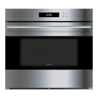
I N S TA L L AT I O N S P E C I F I C A T I O N S
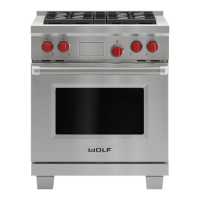
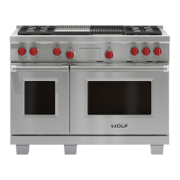
Wolf dual fuel ranges come in 762 mm,
914 mm, 1219 mm an d 1524 mm widths.
Illustrations on pages 4–
7 provide the overall
dimensions and installation specifications for
each width of dual fuel range.
Each range is designed to fit betwee n cabinets
set at the distance specified by the unit. For
example, a 914 mm range will fit a 914 mm
opening. The exception is th e 1524 mm unit
which will requir e a 1530 m m opening.
IMPORTANT NOTE:
Cabinet opening dimen-
sions shown in the installation specificatio ns
illustrations must be used. These dimensions
provide for required clearanc
es.
Each unit is designed with a terminal block on
the rear of the ra nge. Have a qualified electri-
cian or installer w ire your unit from the electri-
cal supply, through the knockout in the unit
base and to the te rminal block on the range.
IMPORTANT NOTE:
Locate the electr ical
supply within dimensions shown in the
installation specifications illustration s and
flush with back wall.
Refer to the installation specifications illustra-
tion for your model on pages 4–7 for the e x
act
rough opening dimensions and location of the
gas supply and electrical.
Wolf dual fuel ranges using natural gas will
operate up to an a ltitude of 2438 m without
any adjustment. Natural gas and LP gas instal -
lations from 2438 m to 3353 m need the high
altitude conversion kit.
I N S TA L L AT I O N I N S T R U C T I O N S
I N S TA L L AT I O N S P E C I F I C A T I O N S
M I N I M U M C L E A R A N C E S
IMPORTANT NOTE:
Caution must be used in
planning the proper installation of the Wolf
dual fuel range to avoid fire or damag
e to
adjacent cabinetry or kitchen equipment.
Be sure to follow the minimum clearances
established in the finished rough opening
dimensions.
For installation against a rear combustible
surface a 254 mm classic stainless steel riser
must be used. Refer part number 804387.
Refer to the installation specifications illustra-
tion for your model on pages 4–7 for the exact
rough op ening dimensions.
Maintain the following clearanc es to
combustible materials:
Minimum 457 mm clearance from bottom
of upper cabinet to countertop, within
152 mm minimum side clearance.
Minimum 762 mm clearance between coun-
tertop and bottom of wood or metal
cabinet, which is protected by not less than
6 mm flame retardant millboard covered
with not less than No. 28 MSG sheet steel,
.4 mm stainless steel, or .6 mm aluminum
or .5 mm copper.
Minimum 914 mm clearance between coun-
tertop and bottom of an unprotected wood
or metal cabinet.
Bottom of ventilation hood must be
600 mm minimum to 914 mm maxi mum
from countertop.
I S L A N D | P E N I N S U L A I N S T A L L A -
T I O N S
For island installations,
the range should
not be installed within an enclosure ha ving an
adjacent rear wall less than 305 mm from the
rear of the unit t hat rises above the countertop.
For peninsula installations,
the range must
have a 152 mm mini mum clear ance to the side
wall, left or right side, and 305 mm minimum
clearance to the rear wall.
Refer to the instal lation specificatio ns illustra-
tion for your model on pages 4–7 for the exact
rou
gh opening dimensions.
Failure to locate the range without the
proper clearances will result in a fire
hazard.
 Loading...