9
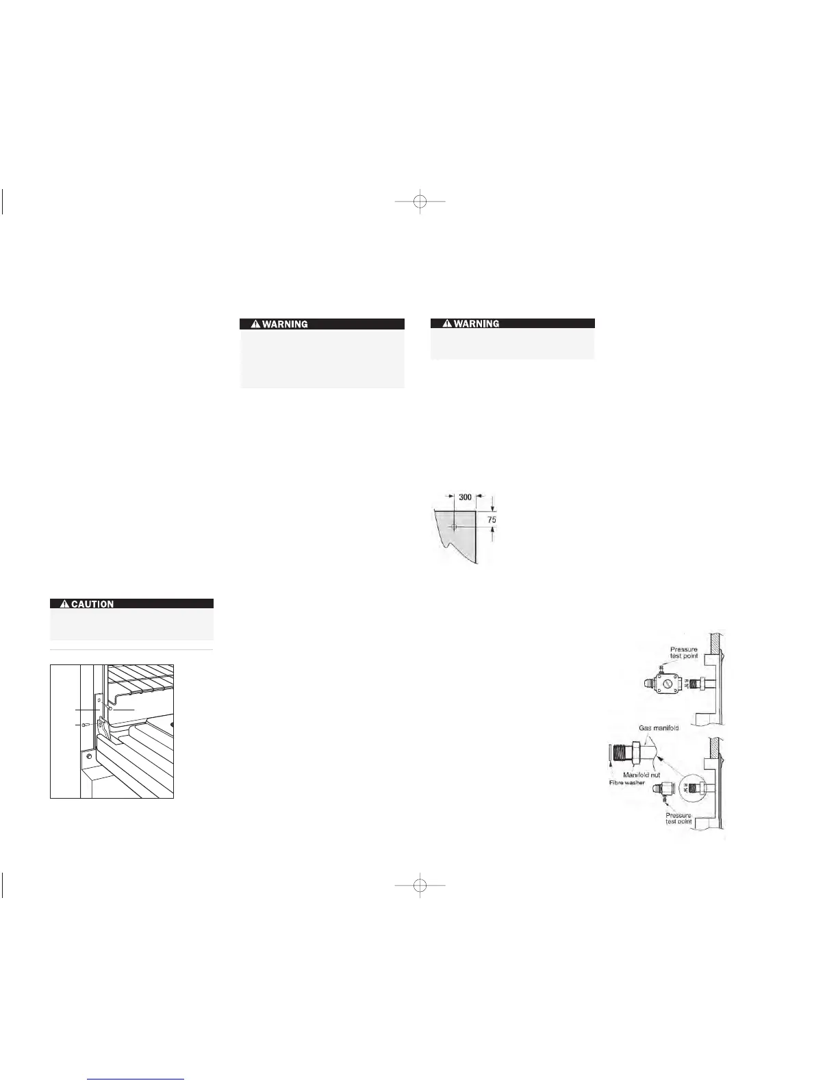
O V E N D O O R R E M O V A L
If removal of the oven door(s) is necess ary,
follow these steps:
1)
Remove the lower kickplate assembly to
access the lower hinge retainer mounting
screws.
2)
Open the oven door to its fully opened
position and remove both upper and lower
hinge retainer mounting screws. The oven
gasket may have to be moved slightly to
access the bottom screws.
3)
After removing the mounting screws, move
the hinge retainer plate forward slightly.
The hinge retainer plate will remain on the
door hinge assembly after the mounting
screws have been removed.
4)
Insert the supplied door hinge pin through
the hole in the app
ropriate hinge arm. Refer
to the illustration below.
5)
Carefully close the oven door to about a
60° angle from horizontal and lift the door
away from the oven. A slight rocking
motion may be required for removal.
6)
For 1219 mm and 1524 mm ranges,
complete these steps for both oven doors
IMPORTANT NOTE:
The dual fuel range must
be connected to a regulated gas supply.
The rating plate, located rear of removable
lower panel, has information on the type of
gas that should be used. If this information
does not agree with the type of gas available,
check with the local gas supplier. A duplicate
pl
ate can be attached to the inside top of an
adjacent cupboard.
This appliance appliance must be installed in a
position with the proper level of ventilation. Do
not obstruct the flow of combustion and venti-
lation air.
The gas pressure regulator supplied with the
appliance must be installed in line with the gas
pipe. (N.G. only).
If the appliance cannot be adjusted to perform
correctly contact Multyflex or the local gas
utility. For service contact telephone number
please refer page 13.
For pressure testing in excess of 3.5 kPa (1/2”
psig) the appliance and its individual shut-off
va
lve must be disconnected from the gas
supply piping system. For pressure testing of
the gas piping system at pressures equal to or
less than 3.5kPa (1/2”psig) the appliance must
be isolated from the gas supply system by
closing its individual shut off valve during any
pressure testing.
The appliance should not be connected to a
combustion product evacuation system.
Instruct the user in the operation of the appli-
ance before leaving..
EXPLOSION HAZARD —
Securely tighten all gas connections.
Failure to do so can re sult in explosion,
fire or death.
G A S SU P P LY R E Q U I R E M E N T S G A S SU P P LY C O N N E C T I O N
I N S TA L L AT I O N I N S T R U C T I O N S
Hinge
Retainer
Plate
Upper Mounting
Screw
Hinge
Pin
Kickplate
Oven doo r removal .
Do not lift or carry the oven door by the
door handle.
Never test for a gas leak with a match or
other flame.
Gas co nnection:
The cooktop is adjusted to operate on the gas
type specified on the gas type label located on
the bottom of the unit. If in doubt as to the
type of gas available contact the network
operator or gas supplier for confirmation of
gas type.
The cooktop must be
connected to the gas
supply with upstream
connection of an isola-
tion valve in accordance
with the respectively
valid regulations. We
recommend that the
isolation valve be fitted
prior to the cooktop to
enable isolation of the cooktop from the gas
supply. The valve must be easily accessible at
all times.
Thi
s appliance may be connected with a hose
assembly, class B or class D in accordance to
AS/NZS 1869. If connected with a hose assembly ensure that the gas
supply connection point is accessible
with the appliance installed.
The position of the inlet connection is
measured from bottom RH rear of unit,
75 mm centre line from rear and 300 mm
centre line from RH side.
Fit regulator (N.G.) or Propane fitting (Propane)
directly to the R1/2” connection. direction for
gas flow is indicated on the rear of the regula-
tor.
Check correct operation of each burner individ-
ually and in combination. Burner flames should
be clear blue, with no yellow tipping. If the
burners show any abnormality check that
burner heads are correctly located and refer to
the ‘trouble shooting’ guide on page 26 & 27 of
the Use and Care manual. If satisfactory
performance can not be obtained, contact
Multyflex or the local gas utility. For service
contact number refer page 13 of this booklet.
Note: These burner have no aeration adjust-
me
nt.
It should be expressly noted that we cannot
accept any liability for direct or indirect damage
caused by wrong connection or improper instal-
lation. When being repaired, the appliance must
always be
disconnected
from the main
gas and electric-
ity supply; if
required,notify
our customer
service.
 Loading...