Do you have a question about the Wood-mizer Slab-Mizer MB200 and is the answer not in the manual?
Explains the purpose and scope of the operations manual for the Wood-Mizer planer.
Provides contact information and procedures for obtaining customer service and support for the planer.
Lists global headquarters and branches for Wood-Mizer customer support and sales.
Details how to identify the planer using model, serial, and revision numbers for proper referencing.
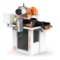
Outlines the technical data, capacities, and requirements of the MB200 planer.
Presents a detailed diagram with all physical measurements of the MB200 planer.
Details the limited product warranty terms, conditions, and coverage for the MB200 planer.
Lists specific components and conditions not covered by the limited warranty.
Covers warrantor's obligations for defects and disclaims implied warranties.
Outlines purchaser's rights under the warranty and company's right to make design changes.
Explains how the warranty agreement is interpreted and supersedes prior agreements.
Explains the meaning of various symbols and signal words used for safety instructions in the manual.
Provides general safety guidelines for operating and maintaining the planer.
Emphasizes the importance of wearing appropriate protective clothing and accessories during operation.
Covers safety precautions for the planer's environment, including cleanliness and hazard avoidance.
Instructs on maintaining the condition and visibility of safety labels on the machine.
Warns about the importance of securely clamping heavy slabs before planing.
Outlines the mandatory lockout procedures for electrical safety during maintenance and servicing.
Details the step-by-step sequence for locking out equipment before maintenance.
Provides steps for safely returning locked-out equipment to normal operating condition.
Explains the specific lockout procedures required when more than one person is involved.
Guides through the process of safely removing the planer from its shipping packaging.
Provides instructions for connecting multiple bed sections to form the main frame of the planer.
Details the process of attaching the side rail strips to the assembled bed sections.
Instructs on how to attach the left, right, and center leg assemblies to the planer bed.
Guides on positioning and securing the head stops at each end of the bed section.
Explains how to attach and position the clamps used for securing material to the planer bed.
Describes the method for adjusting the planer legs to ensure the bed section is level.
Details the procedure for safely placing and securing the gantry onto the assembled bed section.
Instructs on securing the head retainers to the bed assembly after the gantry is in place.
Provides steps for connecting and routing the feed chains on both sides of the table and gantry.
Guides on preparing a firm, level area and adjusting the bed frame for optimal planer placement.
Details site preparation and contractor requirements for the planer's electrical connection.
Specifies electrical codes, fused disconnects, and wiring connections for the planer's power supply.
Explains how to attach the vacuum hose to the vacuum hose arm using clamps or zip ties.
Provides instructions for fitting the orbital balance and sanding pad onto the sanding stud.
Details the sequence of switch operations to safely power on the planer unit.
Explains how to control the planer's forward and backward movement using the pendant joystick and speed control.
Describes how to operate the planer's side-to-side movement using the pendant joystick.
Guides on manually adjusting the cutter head height using the hand turning wheel.
Explains how to activate and deactivate the cutter head using the pendant's motor start and stop buttons.
Details steps to convert the planer for manual operation of cross feed and power feed.
Explains how to perform sanding operations manually or automatically, and adjust sanding pressure.
Provides guidance on keeping machine components clean and lubricated for optimal performance.
Covers checking and adjusting the cross feed rope for proper tension and lubrication of cam bearings.
Instructs on lubricating the lead screw for smooth operation of the head's vertical movement.
Details the procedure for replacing worn cutter inserts and rotating them for fresh edges.
Lists common planing issues, their causes, and recommended solutions for the planer.
Outlines steps to realign the cutter head for optimal planing and sanding results.
Describes how to adjust set screws to align the cutter head's front and rear positions.
Details adjusting cam nuts for proper side-to-side alignment of the cutter head.
Explains how to measure and adjust the scale's sight line for accurate depth settings.
Guides on adjusting the dust head position relative to the material surface for dust collection.
| Model | MB200 |
|---|---|
| Operation | Manual |
| Max Cant Width | 60 inches |
| Bed Length | 20 feet |
| Blade Width | 1.5" (38 mm) |
| Power Source | Electric |