Do you have a question about the Wood-mizer BMT200 and is the answer not in the manual?
Details the purpose and scope of the manual, including its relationship to previous information.
Provides contact information, office hours, and procedures for obtaining service and support.
Covers essential safety instructions, including hazard symbols, warnings, and precautions for operation.
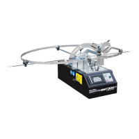
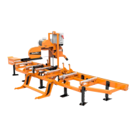
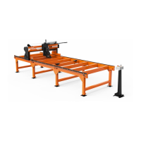
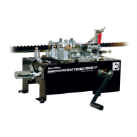
Identifies and illustrates the major components of the dual toothsetter machine.
Details the physical dimensions, weights, and technical specifications of the toothsetter models.
Step-by-step guide for assembling the dual toothsetter, including blade support arms.
Covers procedures for blade installation, manual, and auto feed operation of the toothsetter.
Details the process for calibrating the tooth set master gauge and the dual setter assemblies.
Outlines regular maintenance tasks, including cleaning, lubrication, and checks for wear.
Describes how to check the proper operation of safety features like the Emergency Stop button.
Lists all parts for the complete dual toothsetter assembly, referencing specific sections.
Details individual components and their part numbers within the main toothsetter assembly.
Lists all parts and their respective numbers for the base housing assembly.
Provides a breakdown of parts for the feed drive assembly, including diagrams and part numbers.
Lists replacement parts for the blade setter mechanisms, with diagrams and part numbers.
Details the components and part numbers for the blade support arm assemblies.
Lists all parts and their respective numbers for the clamp assembly.
Provides a breakdown of parts for the index assembly, including diagrams and part numbers.
Details the components and part numbers for the blade support arm assemblies.
Lists replacement parts for the AC 120V auto feed control system.
Lists replacement parts for the AC 220V auto feed control system.
Lists replacement parts for the DC auto feed control system.
Details components and part numbers for the AC auto feed control panel.
Lists replacement parts for the AC auto feed motor.
Lists replacement parts for the DC auto feed motor.
Lists all components and their respective part numbers for the toothsetter gauge assembly.
Diagram showing the electrical connections and components for the AC 120V system.
Diagram showing the electrical connections and components for the AC 220V system.
Diagram illustrating the electrical circuit and components for the DC system.
Visual layout of electrical components within the control box for AC systems.
Visual layout of electrical components within the control box for DC systems.
An itemized list of electrical components used in AC systems with their part numbers.
An itemized list of electrical components used in DC systems with their part numbers.
| Brand | Wood-mizer |
|---|---|
| Model | BMT200 |
| Category | Industrial Equipment |
| Language | English |