Do you have a question about the Wood-mizer LubeMizer and is the answer not in the manual?
Detailed steps for mounting and securing the LubeMizer control box.
Wiring instructions for LubeMizer control box based on sawmill revision (G9.00+, H1.00+, H4.00+, A1.00+).
Wiring instructions for LubeMizer control box based on sawmill revision (F7.00-G8.00, F8.00-G9.00, G1.00-H3.00).
Wiring instructions for LubeMizer control box based on sawmill revision (F7.00+, F8.00+, G1.00+).
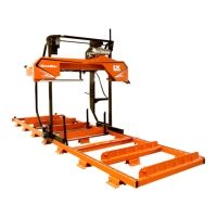
Procedure for installing the lube pump and associated wiring on LT30/LT40 sawmill models.
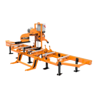
Procedure for installing the lube pump and associated wiring on LX450 sawmill models.
Steps for converting the water lube bottle and installing hose lines on LT30/LT40 models.
Instructions for routing and installing the lube hose lines on LX450 sawmill models.
Final steps for LubeMizer installation, including reassembly, safety checks, and filling the water bottle.
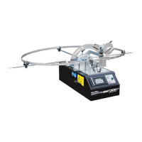
Overview of the LubeMizer system, its function, flow rates, and operation for blade lubrication.
Guidance on using Wood-Mizer Lube Additive and windshield washer fluid for performance and freeze protection.
Procedure for cleaning the LubeMizer system's filter to maintain optimal lubricant flow.
Diagram and part numbers for the LMS-HP/LMS-A pump assembly.
Diagram and part numbers for the LMS-LX pump assembly.
Diagram and part numbers for the LMS-HP/LMS-A filter assembly.
Diagram and part numbers for the LMS-LX filter assembly.
Diagram and part numbers for the LMS-A Blade Guide Block Assembly (Rev. A.01+).
Diagram and part numbers for the LMS-A Blade Guide Block Assembly (Rev. A.00).
Diagram and part numbers for the LubeMizer Control Box Assembly (LMS-A, LMS-RA, LMS-LX).
List of electrical components with Wood-Mizer part numbers and descriptions for the LubeMizer system.
Detailed wiring diagram for the LubeMizer control circuit, including component connections.
Explanation of electrical symbols used in LubeMizer system diagrams for clarity.
| Brand | Wood-mizer |
|---|---|
| Model | LubeMizer |
| Category | Industrial Equipment |
| Language | English |