Do you have a question about the Woodward MSLC-2 and is the answer not in the manual?
Describes hazards, safety instructions, and precautions for operating the equipment.
Details precautions for specific situations and provides general advice.
Provides guidance on checking for the latest manual revision.
Defines key terms like WARNING, CAUTION, and NOTE.
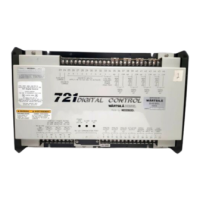
Describes the purpose and system context of the MSLC-2.
Lists original and additional functions of the MSLC-2 control unit.
Explains the synchronizer's role and basic operation.
Details the MSLC-2's load control modes and functions.
Explains the MSLC-2's process control capabilities.
Describes the MSLC-2's var and power factor control modes.
Covers system architecture, addressing, and segmenting rules.
Defines how MSLC and DSLC devices interact within a system.
Outlines the process for configuring the unit using PC software.
Provides steps for installing the necessary configuration software.
Guides users on launching and setting up the software.
Details methods for establishing communication between PC and MSLC-2.
Explains how to monitor unit data using the software.
Describes how to check the unit's firmware and hardware versions.
Introduces the hierarchical menu system for parameter access.
Describes the main screen of the MSLC-2 interface.
Details parameters for synchronizer adjustments.
Covers parameters for load control functions.
Explains parameters for process control configuration.
Details parameters for reactive power and voltage regulation.
Covers settings related to system parameters and interfaces.
Describes settings for analog input signals.
Covers general electrical parameter measurements.
Explains how to monitor system status, modes, and alarms.
Provides crucial precautions for handling sensitive electronic components.
Instructions for safely unpacking the MSLC-2 unit.
Guidelines for selecting an appropriate installation environment.
Describes the physical dimensions and mounting details of the MSLC-2 housing.
Details the mounting procedure for the MSLC-2 unit.
Illustrates the layout and function of the unit's terminals.
Explains the meaning of the status indicator LEDs on the unit.
Provides schematics for connecting the MSLC-2 unit.
Details wire size conversion and general connection information.
Explains the power supply requirements and connection details.
Describes how to connect and configure voltage measurement inputs.
Describes how to connect and configure current measurement inputs.
Explains the concept and calculation of power factor.
Describes the configuration and function of discrete inputs.
Describes the terminal assignments and functions of relay outputs.
Details the configuration of analog input signals.
Describes the various communication interfaces of the MSLC-2.
Outlines the menu steps for initial configuration.
Guides on configuring basic segment numbers for system segmentation.
Details initial setpoints for the synchronizer.
Details initial setpoints for load control.
Details initial setpoints for process control.
Details initial setpoints for var/PF control.
Describes steps to verify measurements and basic operation.
Guides on tuning synchronizer functions.
Guides on verifying and tuning voltage matching.
Guides on setting up load control functions.
Details the configuration for import/export load control.
Explains how to set up and tune the process control function.
Guides on setup and adjustment of var/PF control.
Details configuration for power factor control at the utility.
Describes the process for setting var control at the utility.
Introduces the concept and conditions for synchronization.
Explains how generator and bus matching occurs.
Describes the different synchronizer operating modes.
Explains the importance and process of voltage matching.
Details the configuration for phase matching synchronization.
Explains the slip frequency synchronization method.
Describes the synch-check function for proper synchronization.
Covers parameters and alarms related to breaker closing attempts.
Details conditions that trigger dead bus closing alarms.
Explains the auto re-synchronization feature.
Describes the reclose limit alarm functionality.
Details the timers used in the synchronizer function.
Provides a flowchart for GCB closure logic.
Explains the intelligent ramps for controlled status changes.
Describes the conditions and process for manual synchronization.
Explains how to manually close the breaker.
Introduces the real power control modes.
Explains the interaction between MSLC-2 and DSLC-2 for load control.
Details the base load mode operation and setup.
Explains the import/export mode operation.
Covers functions for automatic power transfer between modes.
Explains the local unload function.
Introduces reactive power control modes.
Details the constant generator power factor control setup.
Explains how MSLC-2 adjusts power factor references.
Explains how MSLC-2 adjusts var references.
Introduces the process control function.
Explains the process control operation and logic.
Introduces the DSLC-2 / MSLC-2 system features.
Explains system rules and segmentation philosophy.
Illustrates system configurations without segmenting.
Illustrates system configurations with segmenting.
Shows an example of generators connected in a ring.
Details extending windows for closing the last breaker in a ring.
Illustrates system configurations that are not supported.
Explains PLC remote control using communication interfaces.
Explains PLC remote control using RS-485 Modbus.
Explains PLC remote control using Ethernet Modbus/TCP.
Lists the available communication interfaces.
Describes the Ethernet interfaces for network communication.
Details the RS-485 interface for Modbus communication.
Details the RS-232 interface for service and Modbus.
Describes behavior in redundant bus topology when a failure occurs.
Describes behavior in single bus topology when a failure occurs.
Describes the overview pages for DSLC2/MSLC2 status.
Explains the information provided on the ToolKit homepage.
Details how to monitor alarms via ToolKit.
Outlines the process for setting up the communication network.
Describes the distributed control architecture for load sharing.
Details monitoring functions for load sharing.
Provides general information about load sharing parameters.
Explains Modbus protocol basics.
Details the Modbus address ranges for visualization and configuration data.
Details how to send setpoints via communication interfaces.
Explains actions when interface control is lost.
Details procedures to restore interface control.
Guides on setting individual parameters via Modbus.
Details the procedure for remote reset using Modbus.
Covers Modbus parameters for RS-232 interface.
Covers Modbus parameters for RS-485 interface.
Covers Modbus TCP/IP parameters for Network A.
Covers Modbus TCP/IP parameters for Network B.
Explains the feature for adapting phase angle measurement.
Describes the namespaces used for parameter grouping.
Explains the unique parameter identifier.
Describes the text labels for parameters.
Explains the valid range for parameter values.
Describes the default parameter settings.
Explains the possible data types for parameters.
Describes the minimum code level required for parameter access.
Describes available technical support services.
Details product training offerings.
Explains on-site field service support.
| Brand | Woodward |
|---|---|
| Model | MSLC-2 |
| Category | Control Unit |
| Language | English |