Manual 37444F MSLC-2 - Master Synchronizer and Load Control
© Woodward Page 71/226
Power Control Monitoring
The High load limit alarm specifies if the high load limit alarm will
activate (energize) the “High Limit” relay (Terminal 44).
The High load limit PU is the import/export load level where (if en-
abled) the “High Limit” relay is energized and the high limit alarm
is activated. The percentage value relates to system A rated load
(parameter 1752).
The High load limit DO is the import/export load level where (if en-
abled) the “High Limit” relay is de-energized and the high limit
alarm is deactivated. The percentage value relates to system A
rated load (parameter 1752).
The Low load limit alarm specifies if the low load limit alarm will
activate (energize) the “Low Limit” relay (Terminal 45).
The Low load limit PU is the import/export load level where (if en-
abled) the “Low Limit” relay is energized and the low limit alarm is
activated. The percentage value relates to system A rated load
(parameter 1752).
The Low load limit DO is the import/export load level where (if en-
abled) the “Low Limit” relay is de-energized and the low limit
alarm is deactivated. The percentage value relates to system A
rated load (parameter 1752).
Load limit switch specifies if the “High Limit” and “Low Limit” re-
lays will activate on high or low limit alarm.
Gen load
high limit
alarm
Generator load high limit alarm specifies if the generator high load
limit alarm will activate the “High Limit” relay (Terminal 44).
The generator high limit alarm is activated when the MSLC-2 is re-
quired to output a system load of 100% to the DSLC-2 controls in
order to meet its reference.
NOTE: The “Alarm” relay includes additional the self-test function.
Alarm active means relay open.
Generator load low limit alarm specifies if the generator low load
limit alarm will activate the “Low Limit” relay (Terminal 45).
The generator low limit alarm is caused when the MSLC-2 is re-
quired to output a system load of 0% to the DSLC-2 controls in or-
der to meet its reference.
Generator load limit switch specifies if the high and low limit
alarms will activate the “Load Switch 1” or “Load Switch 2” relay
when the system load setpoint reaches 100% or respectively 0%.
Generator Load switch 1 PU is the system load level where the
“Load Switch1” relay is energized.
Generator Load switch 1 DO is the system load level where the
“Load Switch1” relay is de-energized.
Generator Load switch 2 PU is the system load level where the
“Load Switch2” relay is energized.
Generator Load switch 2 DO is the system load level where the
“Load Switch2” relay is de-energized.
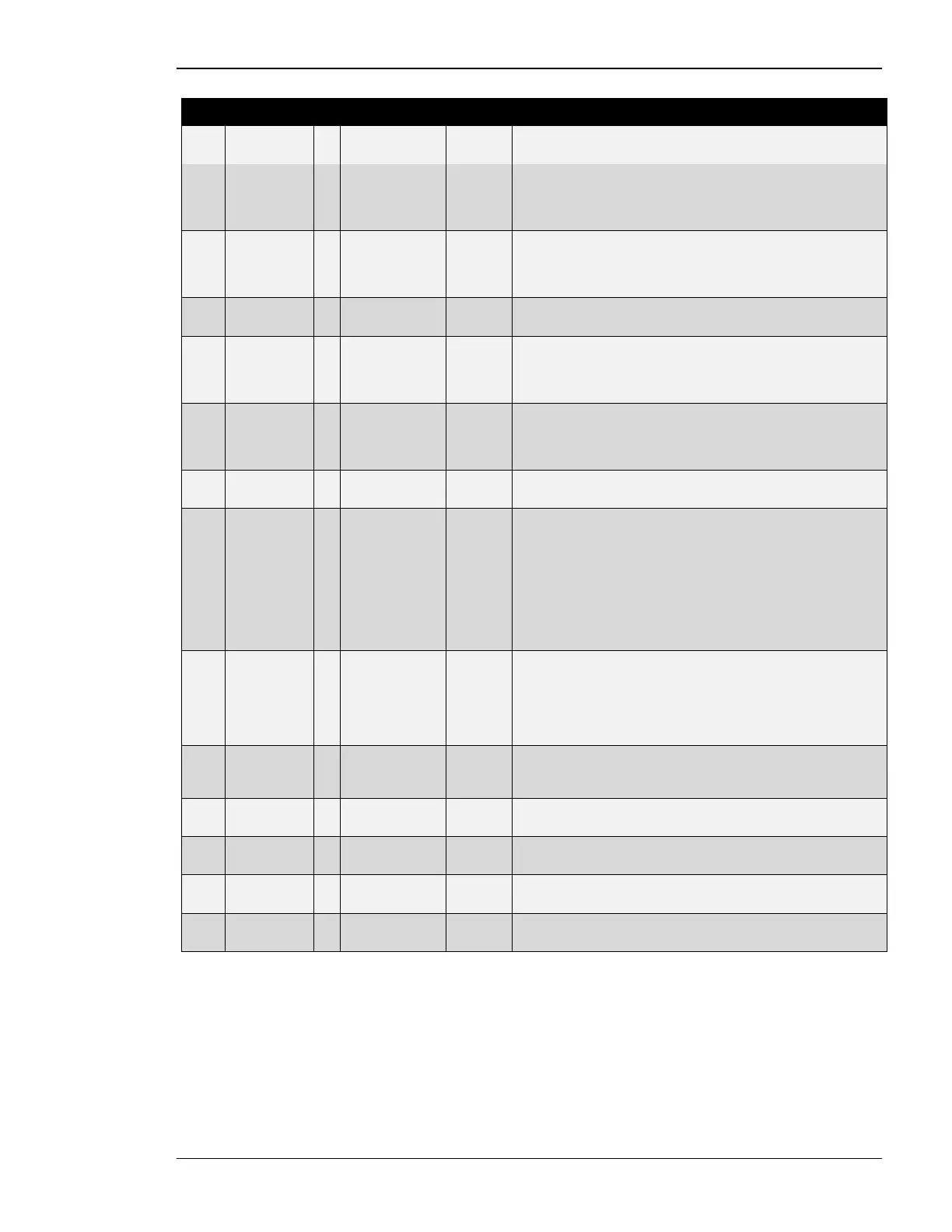
Table 3-19: Parameter – load control – power control monitoring

 Loading...